


 523 / 582

BETA Monitoring
Monitoring of Plants and Devices
14/27
Siemens ET B1 · 10/2008
14
■
Dimensional drawings
5
TT3 472
■
Schematics
■
More information
Function charts
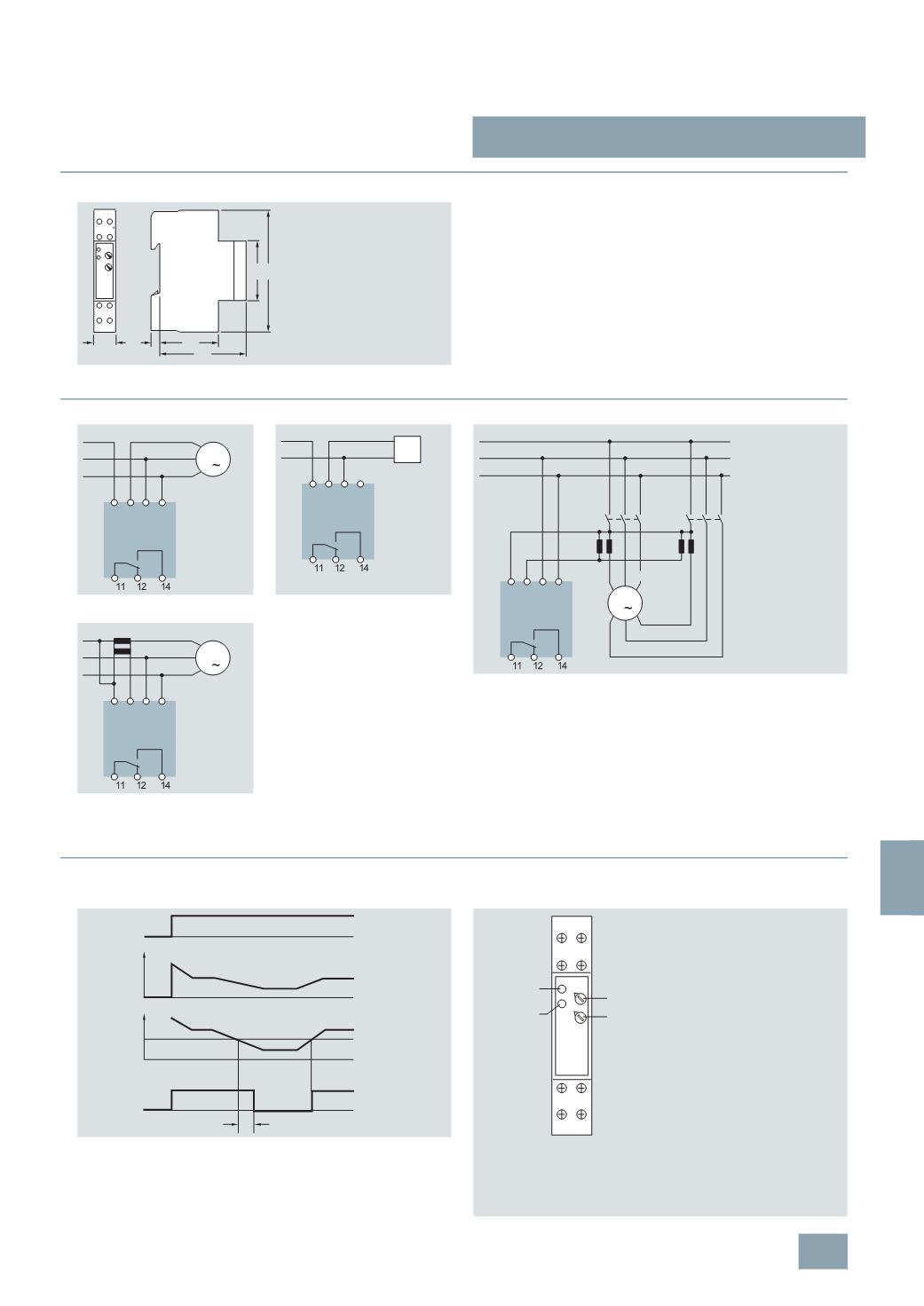
If the p.f. value set at the p.f. controller is fallen below for the duration of
the set response delay, the output relay switches to the alarm state and
the red LED lights up. Contact 11–14 closes and the red LED lights up.
Front view
L3
L1 L1
12
141
18
5 43
45
90
I2_11528b
1
L2
64
Connection of three-phase load
Connection of single-phase load
Connection of motors with separate windings
Connection of three-phase load with
external current transformer, whereby
the winding sense of the current trans-
former must be taken into account.
L1 L1' L2 L3
L1
M
3
L2
L3
I2_11524b
L1 L2 L3
L
N
I2_11525b
L1'
Load
L1 L1' L2 L3
L1
M
3
L2
L3
K k
l
L
K k
l
L
1
W1
1
V1
1
U1
2
W1
2
V1
2
U1
I2_11527b
Low
Speed
High
Speed
L1 L1' L2 L3
L1
M
3
L2
L3
K L
k l
I2_11526b
11-14
11-12
t
y
U
(
L1/L2/L3)
I
(
L1/L2)
I2_11523b
Trip
p.f.
L3 L2
11
L1 L1'
14
I2_11973a
12
E1
E2
LED red
LED green
Underloading indicator (p.f. alarm)
LED red:
Response value
E1:
Response delay
t
y
E2:
LED green: Status display (
U
)
5
TT3 472 p.f. controllers
© Siemens AG 2008