


 525 / 582

BETA Monitoring
Monitoring of Plants and Devices
5
TT3 43 thermistor motor protection relays
14/29
Siemens ET B1 · 10/2008
14
■
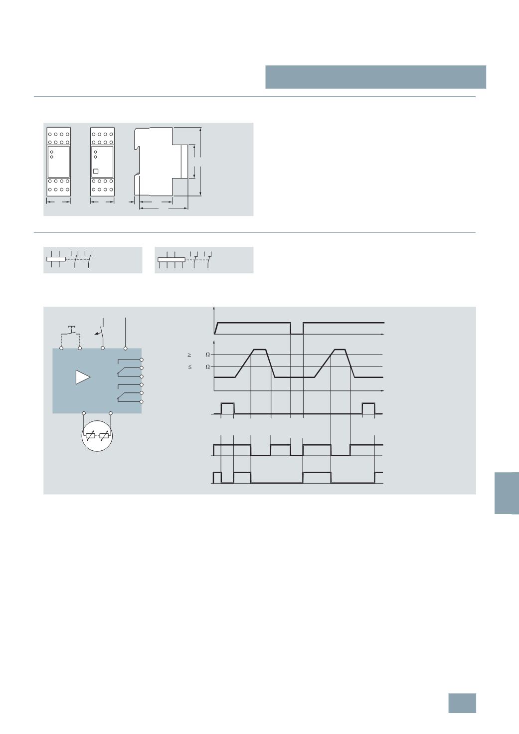
Dimensional drawings
5
TT3 43 thermistor motor protection relays
■
Schematics
Switching example:
5
TT3 431, 5TT3 432
If one of the thermistors (possible for up to 6) reaches the
response temperature, the device switches.
5
TT3 431 (without terminals X1/X2 and without Reset pushbutton)
switches back on after cooling and after the value falls below the
value permanently set for the hysteresis. To switch on prior to this
time, briefly disconnect the power supply.
5
TT3 432 stores the fault and remains switched off until the Reset
pushbutton is pressed.
5
TT3 431
5
TT3 432
36
36
5 43
64
45
90
I2_11530a
A1 P1P2
A1
A1
12
14 11 2421
14 11 24 21
22
12 22
P1P2
X1X2
A2
5
TT3 431
5
TT3 432
A2 A1
P2 P1
14 12 24 22
11 21
A2 A1
P1 P2 X1 X2
14 12 24 22
11 21
L1 N
A1 A2
14
11
12
24
21
22
X2
X1
1...6
v +
M
I2_07041c
Reset
pushbutton
230
V AC
R
I2_07280d
11-14
P1/P2
5
TT3 432: 11-12
11-14
5
TT3 431: 11-12
(
X1/X2)
H
U
t
t
3,2
k
1,8
k
TEST/
RESET
TEST/
RESET
TEST/RESET
pushbutton
Overtemperature/
sensor breakage
Voltage
failure RESET
© Siemens AG 2008