


 496 / 582

BETA Monitoring
Monitoring of Electrical Values
7
LQ3 insulation monitors for medical premises
13/40
Siemens ET B1 · 10/2008
13
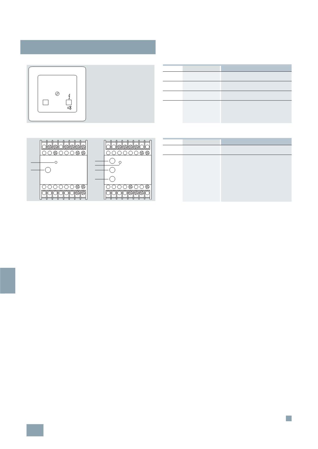
Control elements of the test and signaling combination
Control elements of voltage relay
7
LQ3 360
I2_13996
ON
TEST
LED/pushbutton Meaning
ON
Green LED
The LED lights up if the power supply is
applied
Ground
fault
Yellow LED
Insulation fault: the insulation resistance
of the IT system is too low
Test
Pushbutton for testing the insulation
monitoring devices
Acknowledgement
pushbutton
Pushbutton for acknowledging the
acoustic alarm signal
5
TT3 411
5
TT3 412
N La
Lb
Y1 Y2 11 12
41 42
23 24
33 34
1
2
I2_13717
L3 L2 L1
N
24 11 14
23 31
32
12
2
2
2
1
I2_13720
LED/pushbutton Meaning
1
5
TT3 411: Yellow LED
5
TT3 412: Green LED
The LED lights up if the system is
fault-free
2
Test button
Pressing the test button simulates an
undervoltage. The three-phase 5TT3 412
voltage relay has a test button for each
phase.
© Siemens AG 2008