


 493 / 582

BETA Monitoring
Monitoring of Electrical Values
7
LQ3 insulation monitors for medical premises
13/37
Siemens ET B1 · 10/2008
13
*
You can order this quantity or a multiple thereof.
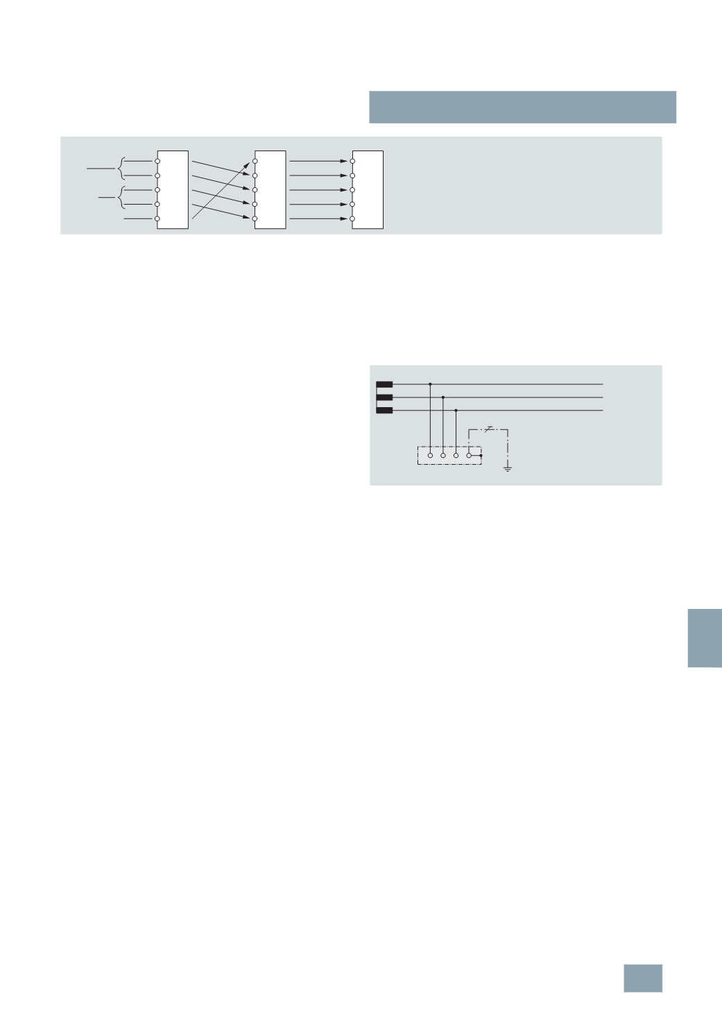
Comparison of the contact assignment of the previously no longer available 7XV9 306, 7XV9 304 und 7XV9 302 test and signaling combinations.
Monitoring of medical premises
Medical premises are all rooms used for the examination or
treatment of persons or animals. As well as doctor's surgeries
and clinics, this includes treatment rooms for hydrotherapy and
physiotherapy and massage rooms.
TÜV approved and safety-tested changeover and monitoring
units ensure the reliable power supply of such premises.
Any insulation monitors and voltage relays installed in these
changeover and monitoring units must meet the requirements of
DIN VDE 0100-710 and IEC 60364-7-710.
The standard DIN VDE 0100-710, published in 2002, divides
medical premises into three groups.
For premises in groups 0 and 1, standard requirements include,
implementation of the system type TN-S and residual current
protective devices (RCD) for protection against excessively high
touch voltages.
The premises of group 2 are defined as follows:
•
The system must not be disconnected in the event of a first
short circuit to frame or to ground or if the general power
supply fails.
•
Repetition of treatment is unacceptable for patients or it is
impossible to obtain results of examinations again.
•
An irregularity (a fault) in the power supply can cause danger
to life.
•
A piece of equipment used for medical purposes, which is
used occasionally for applications in accordance with
DIN VDE 0100-710.2.7, should be assigned to group 2.
Typical locations in group 2 are areas used for anesthesia, oper-
ating and recovery in hospitals, clinics or doctor’s
surgeries, as well as equipment used in veterinary medicine.
Standard DIN VDE 0100-710 makes the following stipulations:
•
Constant monitoring of the supply voltage on the preferred
supply line and on the second supply line.
•
Automatic changeover to the second supply line within a
defined time (< 0.5 s or < 15 s)
•
Reliable operation even if a fault occurs
(
one-fault security).
The switchover device monitors the supply voltage on the
preferred and second supply line for undervoltage and power
failure. As soon as a voltage drop to a defined value is determined,
the voltage relays operate and the switchover device automatically
switches to the second supply line. As soon as the power is
restored on the preferred supply line, the system switches back
to it.
IT system
In the IT system designation, the first letter describes the
grounding conditions of the power source.
I
stands for isolation
of all live parts from the ground or the linking of a point to the
ground over an impedance. The second letter designates the
grounding conditions of the body of the electrical plant.
T means that the body is directly grounded, independent of any
existing grounding of a point of the power source.
Medical IT systems
Standard DIN VDE 0100-710 makes the following stipulations for
a medical IT system in group 2:
•
The medical IT system must be used for socket outlet current
circuits in the patient environment. This also applies for
circuits supplying operating room lights.
•
At least one IT system is required for each area/room group.
•
Separate circuits must be provided for multiple socket outlets.
•
First faults must not lead to disconnection of the system.
The IT system is powered over an isolating transformer or an
independent power source (e.g. a battery). The special feature
here is the fact that no active conductor is directly linked to the
ground in this system. This has the advantage that only a small
residual current can flow in the event of a insulation fault. This is
essentially dictated by the network discharge capacities and is
harmless to patients and staff. The upstream fuse does not
respond so that the power supply, and therefore operation, is
maintained, even in the event of a phase-to-ground fault. The
high reliability of an IT system is ensured by continuous insulation
monitoring. The insulation monitor detects isolation faults as they
develop and promptly signals if a value drops below the limit value
before any further insulation faults can cause an unforeseen
interruption. The temperature of the transformer and the
transformer load continue to be monitored constantly. Any
exceeding of limit values is signaled immediately.
31
32
33
34
35
7
XV9 302
7
XV9 304
7
XV9 306
1
2
3
3
4
5
2
4
5
6
I2_13813a
Test
24
V AC
Fault input
I2_12110
L2
L3
L1
Body
IT system
PE
© Siemens AG 2008