


 489 / 582

BETA Monitoring
Monitoring of Electrical Values
7
LQ3 insulation monitors for medical premises
13/33
Siemens ET B1 · 10/2008
13
*
You can order this quantity or a multiple thereof.
Test and signaling panels
Test and signaling combination for insulation monitors
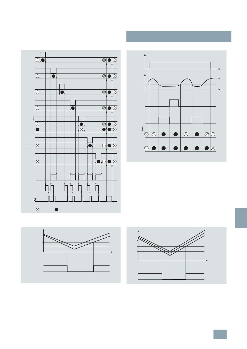
Voltage relays
The voltage relay switches at a phase asymmetry of approx. 6 to
8 %,
regardless of the response values for undervoltage. The
above diagram also shows the timing interval.
7
LQ3 356, 7LQ3 357
X1-L1
X2-L1
X3-L2
X4-L2
X5-
LED 1
LED 2
LED 3
LED 4
LED 5
LED 6
LED 7
LED 8
X11-
X8-
X6-
X7-
I2_13989
>
>
I
Line 1 OK
Line 1 failure
Line 2 OK
Line 2 failure
Test /
lation
Iso-
Over-
temperature
Overload
Output
Horn
Acknowledgement
lamp test
Dark
Bright
SM
7
LQ3 360
X1/X2
ON
E
R
an
R
t
t
U
H
U
Ground fault
Horn
Green
LED
Yellow
LED
Acknow-
ledgement
pushbutton
I2_13990
5
TT3 411
t
U
L
L
b
a
U
N
.3 - .4
.1 - .2
I2_13574
Response
value
Hysteresis
5
TT3 412
t
U
L3
L2
L1
U
N
U
U
11 - 14
11 - 12
I2_13576a
t
on
off
U
N
© Siemens AG 2008