


 495 / 582

BETA Monitoring
Monitoring of Electrical Values
7
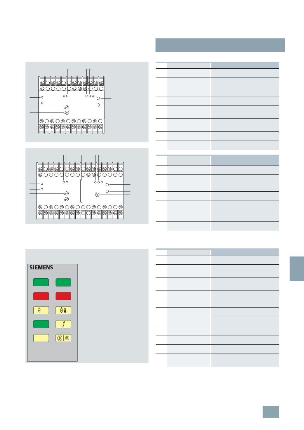
LQ3 insulation monitors for medical premises
13/39
Siemens ET B1 · 10/2008
13
*
You can order this quantity or a multiple thereof.
Control elements for insulation monitors
Control elements of the test and signaling panels
7
LQ3 354
7
LQ3 355
A1
P1 P2
i
k PE PT LT1 LT2
14
24 11
21 34 31 44 41 54 51 64 61
PE‘
L
L‘
A2
52
62
32
42
12
22
1
6
7
10
11
8
9
2
3 4 5
I2_13716
P2 P1
i
k
PE‘
L‘
PE
L
PT LT1 LT2
A1
21 24
31 34
41 44
54 51 64 61
X2 X5
14
22
32
42
52
62
X1
12
11
A2
I2_13814
1 2
5
a
7
8
9
6
11
9
a
10
3 4 5
LED
Meaning
1
Current monitoring
(
green)
Lights up if the current is correct
(
Go-state)
2
Current monitoring
"
>
I
" (
red)
Lights up in the case of overcurrent
3
Insulation monitoring "ON"
(
green)
Lights up when the power supply is
switched on (ready to run)
4
Insulation monitoring "MK"
(
red)
Lights up if a line of the measuring circuit
is interrupted (L, L’, PE, PE’)
5
Insulation monitoring "AL"
(
red)
Lights up in the case of an insulation fault,
R
F
<R
on
(
value has fallen below the
response value)
5
a
Line insulation monitoring
"
R
F
" (
location, yellow,
green)
11-
step LED chain to display the current
resistance
6
Temperature monitoring
(
green)
Lights up when the power supply is
switched on
7
Temperature monitoring
(
red)
Lights up in the event of overtemperature
or an interruption in the sensor circuit
Pushbutton/rotary
regulator
Meaning
8
Rotary regulator
response value ">
I
"
Setting of the response value for current
monitoring
9
Rotary regulator
delay time
Setting of delay time after which the CO
contacts return to their normal position if
the current value exceeds the set
response value.
9
a
Rotary regulator response
value "R
an
k "
Setting of the response value for line
insulation monitoring.
10
"
Test" pushbutton
Pressing the test button simulates an
insulation deterioration in the measuring
circuit (R
F
approx. 40 k ), thus checking
that the line insulation monitor is fully
functional.
11
"
Reset" pushbutton
Deletion of fault if the fault storage is
activated
7
LQ3 356, 7LQ3 357
I2_13995
>
I
7
LQ3 357
line 1
on
line 1
failure
insulation
ok
test
line 2
failure
line 2
on
LED window displays Meaning
Line 1 On
Power supply is implemented over the
preferred infeed
Line 2 On
+ Line 1 Failure
Power supply is implemented over the
second line as the preferred infeed has
failed
Line 1 On
+ Line 2 Failure
Power supply is implemented over the
preferred infeed. However the second
line is no longer available
Line 2 On
+ Line 1 Failure
+ Line 2 Failure
Power supply is implemented over the
second line as the preferred infeed is
faulty. There is undervoltage on the
second line
Overload
Excessive power consumption of the
IT system
Overtemperature
The transformer of the IT system is
overloaded
Insulation is good
The transformer of the IT system is
overloaded
Insulation is defective The insulation resistance of the IT system
is too low
Test
Pushbutton for testing the insulation
monitoring devices
Acknowledgement
pushbutton/lamp test
Pushbutton for acknowledging the
acoustic alarm signal/function test of the
display elements
© Siemens AG 2008