


 75 / 253

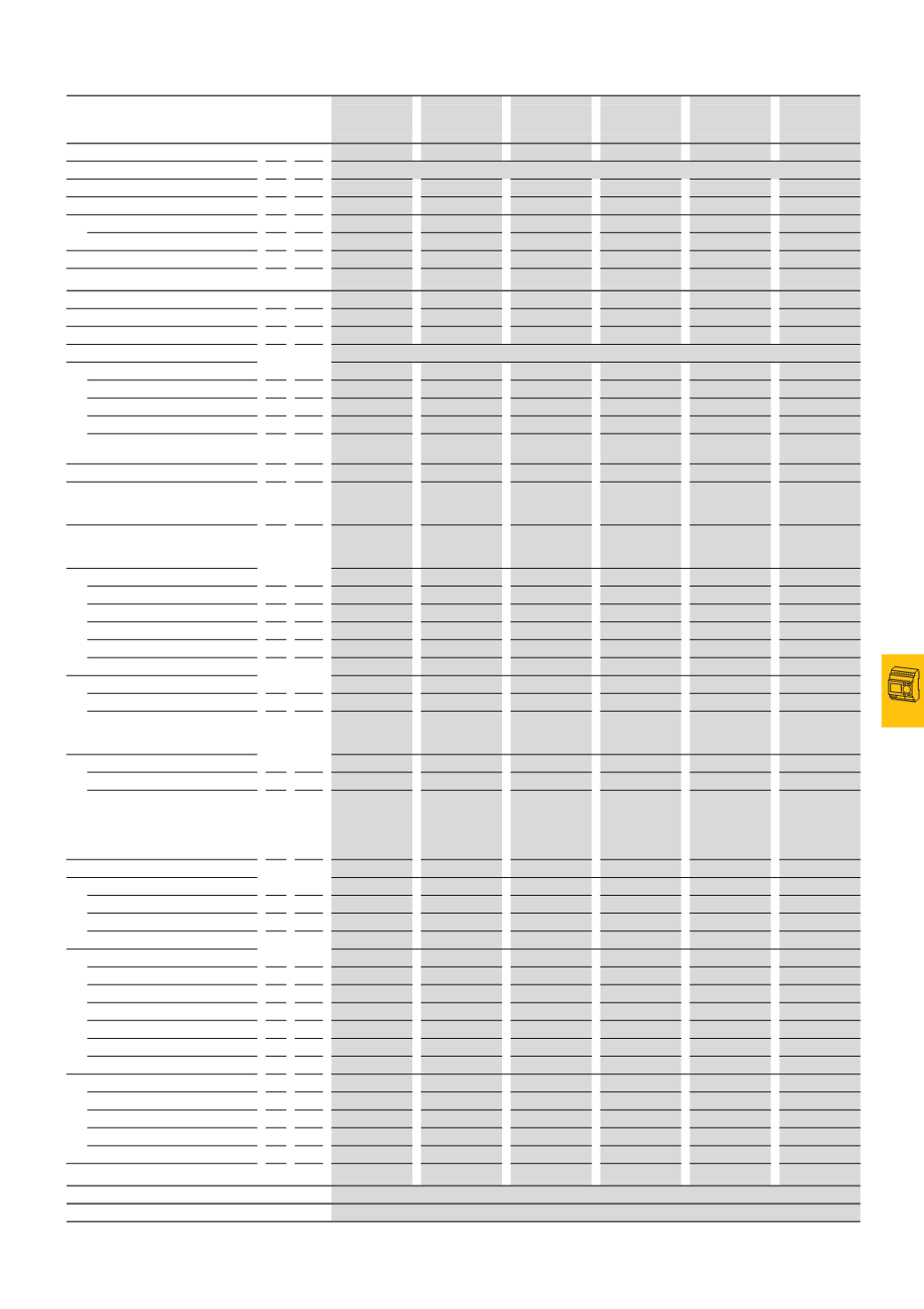
Control relays, multi-function display
Basic devices, expansion devices
2010
CA08103002Z-EN
www.eaton.com...DC...
12/33
...DC...Basicdevices,expansiondevices
EASY410-DC-RE
EASY410-DC-TE
EASY512-DC-… EASY6..-DC-.E EASY7..-DC-… EASY7..-DC-… EASY8..-DC-…
Power supply
Rated operational voltage
U
e
V 24 DC (-15/+20%)
Permissible range
V DC 20.4…28.8
20.4…28.8
20.4…28.8
20.4…28.8
20.4…28.8
20.4…28.8
Ripple
%
≦ 5
≦ 5
≦ 5
≦ 5
≦ 5
≦ 5
Input current
At rated voltage
mA Normally 140
Normally 80
Normally 140
Normally 140
Normally 140
Normally 140
Voltage dips (IEC/EN 61131-2)
ms 10
10
10
10
10
10
Heat dissipation
W Normally 3.5
Normally 2
Normally 3.4
Normally 3.5
Normally 3.5
Normally 3.4
Digital inputs 24 V DC
Number
6
8
12
12
12
12
Inputs can be used as analog inputs
-
2 (
I7, I8)
–
4 (
I7, I8, I11, I12) 4 (I7, I8, I11, I12) 4 (I7, I8, I11, I12)
Status display
LCD display (if provided)
Potential isolation
From power supply
No
No
No
No
No
No
Between digital inputs
No
No
No
No
No
No
From the outputs
Yes
Yes
Yes
Yes
Yes
Yes
From PC interface, memory card,
easyNet, easyLink
–
–
–
–
–
Yes
Rated operating voltage
U
e
V DC 24
24
24
24
24
24
On signal ”0”
U
e
V DC < 5 (R1 - R6)
< 5 (I1 - I8)
< 5 (I1 - I12,
R1 - R12)
< 5 (I1 - I12,
R1 - R12)
< 5 (I1 - I12,
R1 - R12)
< 5 (I1 - I6, I9,
I10) < 8 (I7, I8,
I11, I12)
On signal ”1”
U
e
V DC > 15.0 (R1 - R6)
> 15 (I1 - I6), > 8
(
I7, I8)
–
> 15.0 (I1 - I6, I9,
I10), > 8.0 (I7, I8,
I11, I12)
> 15.0 (I1 - I6, I9,
I10), > 8.0 (I7, I8,
I11, I12)
> 15.0 (I1 - I6, I9,
I10), > 8.0 (I7, I8,
I11, I12)
Input current on signal "1"
R1 - R6 (R12)
mA 3.3 (at 24 V DC)
–
3.3 (
at 24 V DC)
–
–
–
I1 to I6
mA –
3.3 (
at 24 V DC)
–
3.3 (
at 24 V DC)
3.3 (
at 24 V DC)
3.3 (
at 24 V DC)
I7, I8
mA –
2.2 (
at 24 V DC)
–
2.2 (
at 24 V DC)
2.2 (
at 24 V DC)
2.2 (
at 24 V DC)
I9, I10
mA –
–
–
3.3 (
at 24 V DC)
3.3 (
at 24 V DC)
3.3 (
at 24 V DC)
I11, I12
mA –
–
–
2.2 (
at 24 V DC)
2.2 (
at 24 V DC)
2.2 (
at 24 V DC)
Delay time from 0 to 1
Debounce ON
ms 20
20
20
20
20
20
Debounce OFF
ms Normally 0.25
(
R1 - R6)
Normally 0.25
(
I1 - I8)
Normally 0.25
(
R1 - R12)
Normally 0.25
(
I1 - I12)
Normally 0.25
(
I1 - I12)
Normally 0.1
(
I1 - I4), normally
0.25 (
I5 - I12)
Delay time from 1 to 0
Debounce ON
ms 20
20
20
20
20
20
Debounce OFF
ms –
–
–
–
–
Normally 0.1
(
I1 - I4), normally
0.4 (
I5,I6, I9,I12),
normally 0.2 (I7,
I8, I11, I12)
Cable length (unshielded)
m 100
100
100
100
100
100
Frequency counters
Number
–
2 (
I3, I4)
–
2 (
I3, I4)
2 (
I3, I4)
4 (
I1, I2, I3, I4)
Counter frequency
kHz –
< 1
–
< 1
< 1
< 5
Pulse shape
–
Square
–
Square
Square
Square
Incremental counters
Number
–
–
–
–
–
2 (
I1 + I2, I3 + I4)
Counter frequency
kHz –
≦ 1
–
≦ 1
≦ 1
≦ 3
Pulse shape
–
–
–
–
–
Square
Counter inputs I1 and I2, I3 and I4
–
–
–
–
–
2
Signal offset
–
–
–
–
–
90
°
Mark-to-space ratio
–
–
–
–
–
1:1
High-speed counter inputs
Number
–
2 (
I1, I2)
–
2 (
I1, I2)
2 (
I1, I2)
4 (
I1, I2, I3, I4)
Cable length, shielded
m –
< 20
–
< 20
< 20
< 20
Counter frequency
kHz –
< 1
–
< 1
< 1
< 5
Pulse shape
–
Square
–
Square
Square
Square
Cable length (unshielded)
m –
100
100
100
100
100
Relay outputs
→See technical data, relay outputs
Transistor outputs
→See technical data, transistor outputs
Notes
For additional technical data EASY5… and EASY7…→AWB2528-1508D, EASY8…→AWB2528-1423D