


 230 / 253

14/114
Automation products
Digital input modules
Remote I/O XI/ON
2010
CA08103002Z-EN
www.eaton.comRemote I/OXI/ONDigital inputmodules
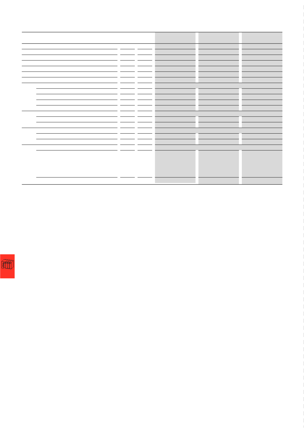
XN-2DI-24VDC-P
XN-2DI-24VDC-N
XN-2DI-120/230VAC
Digital input modules
Channels
Number 2
2
2
Rated voltage at supply terminal
U
L
24
V DC
24
V DC
120/230
V AC
Rated current drawn from supply terminal
1), 2)
I
L
mA
≦ 20
≦ 20
≦ 20
Rated current drawn from module bus
2)
I
MB
mA
≦ 28
≦ 28
≦ 28
Insulation test
U
i
V AC 500
500
1500
Heat dissipation
W 0.7
0.7
1
Input voltage
Input voltage, rated value
24
V DC
24
V DC
120/230
V AC
Low level
-30
V - +5 V
30
V - (U
L
- 11
V)
0 - 20
V AC
High level
11 - 30
V
0 - 5
V
79
V AC - 265 V AC
3)
Frequency range
Hz
-
-
48 - 63
Input current
Low level⁄active level
0
mA - 1.5 mA
0
mA - 1.7 mA
0
mA - 1 mA
High level⁄active level
2
mA - 10 mA
1.8
mA - 10 mA
3
mA - 10 mA
Input delay
t
rising edge
μs
< 200
< 200
< 20000
t
falling edge
μs
< 200
< 200
< 20000
Basic modules
Without C connection
XN-S3...-SBB
2-
conductor proximity
switches (Bero®) can
be connected, with a
permissible quiescent
current of up 1.5 mA.
XN-S3...-SBB
2-
conductor proximity
switches (Bero®) can
be connected, with a
permissible quiescent
current of up 1.5 mA.
XN-S3...-SBB
With C connection
XN-S4...-SBBC
XN-S4...-SBBC
XN-S4...-SBBC
Notes
1)
The supply terminal (U
L
)
provides power for the module electronics and for the
sensors at the inputs. The total current required for each module consists of the
sum of all partial currents.
2)
Part of the XI/ON module’s electronics is supplied with module bus voltage (5 V DC),
the other part through the supply terminal (U
L
).
3)
Max. permissible capacity: 141 nF at 79 V AC/50 Hz; 23 nF at 265 V AC/50 Hz