


 229 / 253

Automation products
Gateways, supply modules
2010
CA08103002Z-EN
www.eaton.comRemote I/O XI/ON
14/113
Remote I/OXI/ONGateways, supplymodules
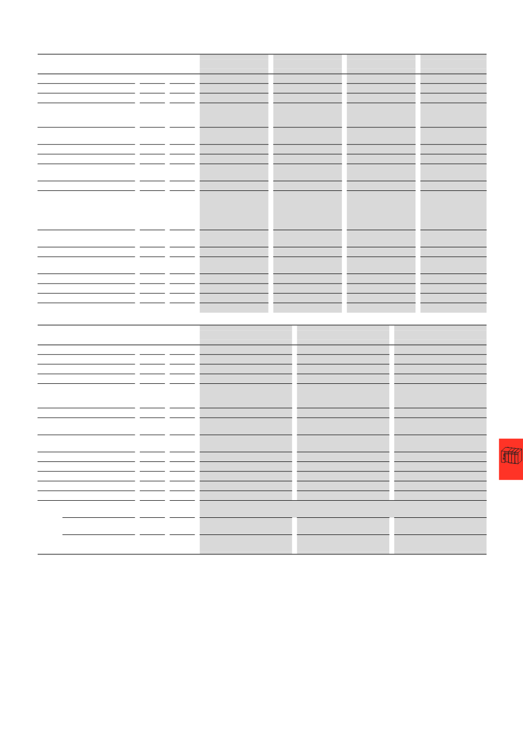
XN-GW-PBDP-1.5MB XN-GW-PBDP-12MB XN-GW-CANOPEN
XN-GW-DNET
XN gateways without built-in supply module
Fieldbus
PROFIBUS-DP
PROFIBUS-DP
CANopen
DeviceNet
Protocol
PROFIBUS-DPV0
PROFIBUS-DPV0
CANopen
DeviceNet
Maximum number of stations
74
modules (XN) of
slice design or
max. length of station: 1 m
74
modules (XN) of
slice design or
max. length of station: 1 m
74
modules (XN) of
slice design or
max. length of station: 1 m
74
modules (XN) of
slice design or
max. length of station: 1 m
Operating voltage
V DC 5 (from bus refreshing
module)
5 (
from bus refreshing
module)
5 (
from bus refreshing
module)
5 (
from bus refreshing
module)
Permissible range
V DC 4.7 - 5.3
4.7 - 5.3
4.7 - 5.3
4.7 - 5.3
Ripple
%
< 5 (to EN 61131-2)
< 5 (to EN 61131-2)
< 5 (to EN 61131-2)
< 5 (to EN 61131-2)
Rated current drawn from module
bus
I
MB
mA
≦ 430
≦ 430
≦ 350
≦ 250
Servicing interface
PS/2 socket
PS/2 socket
PS/2 socket
PS/2 socket
Fieldbus terminals
2
x D-sub 9-pin sockets;
2
x spring-loaded terminal
strips for direct wiring
1
x D-sub 9-pin socket
1
x D-sub 9-pin socket;
1
x D-sub 9-pin plug;
2
x spring-loaded terminal
strips for direct wiring,
5 -
pin
Open style connector
Transfer rate
kBit/s
9.6 - 1500
9.6 - 12000
10, 20, 50, 125, 250, 500,
800, 1000
125, 250, 500
Data transfer rate setting
-
-
Through DIP switch
Through DIP switch
Address assignment
Through two hex rotary
coding switches
Through two hex rotary
coding switches
Through two hex rotary
coding switches
Through two decimal
rotary coding switches
Fieldbus termination
Through D-sub plug
Through D-sub plug
Through D-sub plug
Through DIP switch
Number of parameter bytes
5
5
-
-
Number of diagnosis bytes
3
3
-
-
Address range
1 - 125
decimal
1 - 125
decimal
1 - 127
decimal
0 - 63
decimal
XN-BR-24VDC-D
XN-PF-24VDC-D
XN-PF-120/230VAC-D
Supply modules
Operating voltage
24
V DC
24
V DC
120
⁄230 V AC
System supply
U
SYS
V DC 24
-
-
Permissible range, 24 V DC
U
SYS
V DC 18 - 30
1)
-
-
Permissible range, 5 V DC
U
MB
(
built into
system)
V DC 4.7 - 5.3
-
-
Field voltage
U
L
24
V DC
24
V DC
120/230
V AC
Permissible range
U
L
18 - 30
V DC
18 - 30
V DC
2)
102 - 132
V AC (120 V AC)
195.5 - 253
V AC (230 V AC)
3)
Rated current drawn from module
bus
I
MB
mA
-
≦ 28
≦ 25
Insulation test
U
i
V AC 500
500
1500
Ripple
%
< 5 (to EN 61131-2)
< 5 (to EN 61131-2)
< 5 (to EN 61131-2)
Maximum operating current
I
L
A
10
10
10
Maximum system supply current
I
MB
A
1.5
-
-
Number of diagnostic bits
4
4
4
Base module without gateway
power supply
Without C connection
XN-P3...-SBB
XN-P3...-SBB-B
XN-P3...-SBB
XN-P3...-SBB
With C connection
XN-P4...-SBBC
XN-P4...-SBBC-B
XN-P4...-SBBC
XN-P4...-SBBC
Notes
1)
Permissible range for system supply:
for U
SYS
= 24 V DC: 18 to 30 V DC (to EN 61131-2)
2)
Permissible range for field voltage U
L
:
to EN 61131-2 (18 to 30 V DC)
3)
Permissible range for rated voltage and field voltage U
L
:
to EN 61131-2