


 234 / 253

14/118
Automation products
Analog input modules
Remote I/O XI/ON
2010
CA08103002Z-EN
www.eaton.comRemote I/OXI/ONAnalog inputmodules
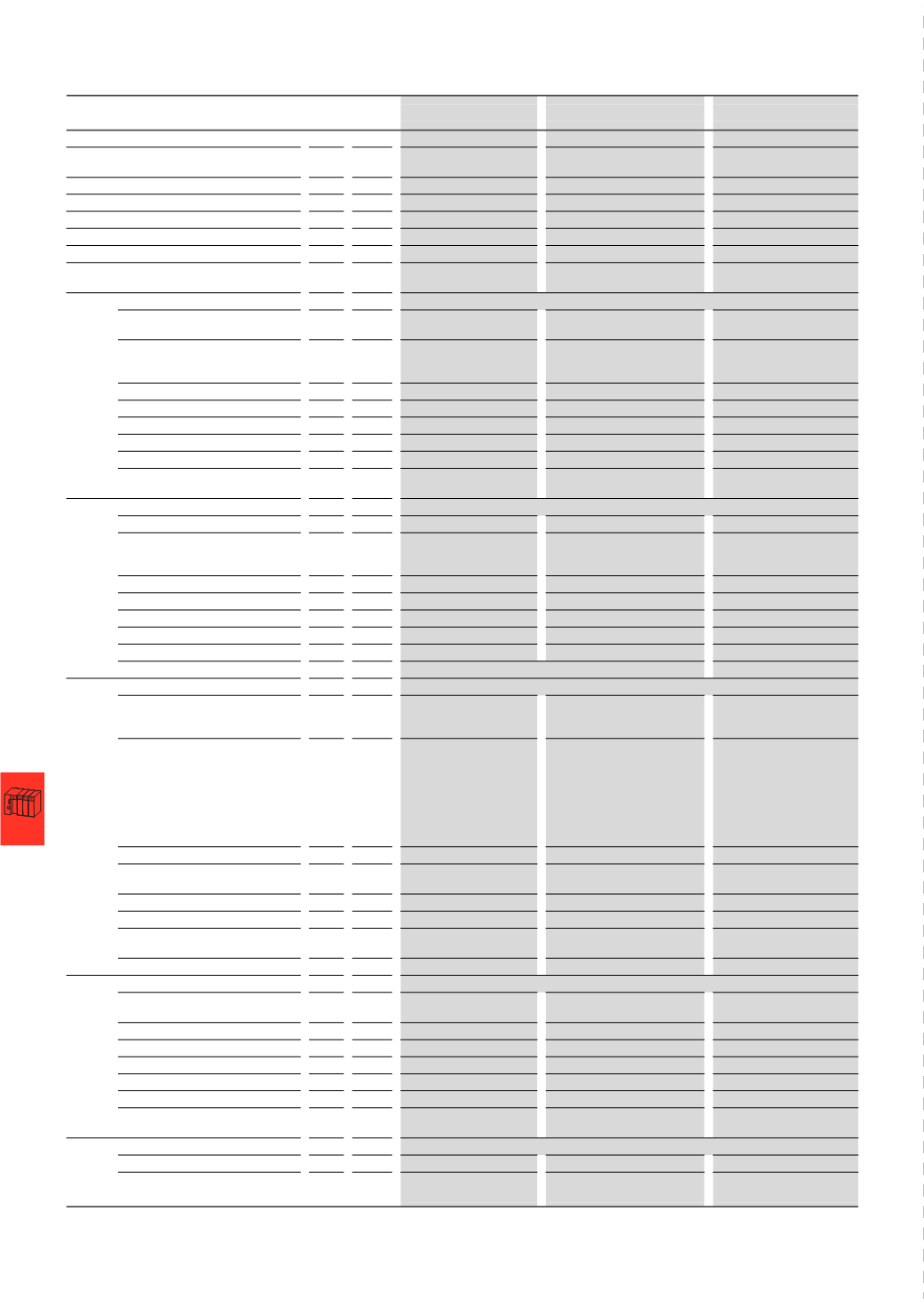
XN-1AI-I(0/4...20MA)
XN-2AI-I(0/4...20MA)
XN-1AI-U(-10/0...+10VDC)
Analog input modules
Measured variables
Current
Current
Voltage
Channels
Number 1
2
1
Rated voltage at supply terminal
U
L
24
V DC
24
V DC
24
V DC
Rated current drawn from supply terminal
1), 2)
I
L
mA ≦ 50
≦ 12
≦ 50
Rated current drawn from module bus
2)
I
MB
mA ≦ 41
≦ 35
≦ 41
Heat dissipation
W < 1
< 1
< 1
Sensor/transmitter supply
Bridged with U
L
and GND
L
of
incoming unit; not protected
≦ 250mA; bridgedwith U
L
andGND
L
of incoming unit; not protected
Bridged with U
L
and GND
L
of
incoming unit; not protected
Voltage measurement
Measurement ranges
-
-
-10 - 10
V DC/0 - 10 V DC
Value representation
-
-
Standard, 16 bit/12 bit
left-aligned
The following can be connected:
-
-
2-/3-/4-
conductor + shield
Maximum input voltage
U
max.
V DC -
-
35
Input resistance
R
L
kΩ
-
-
≧ 98.5 kΩ
Limiting frequency
f
G
Hz
-
-
200
Basic error limit at 23 °C
% -
-
< 0.2
Temperature coefficient
-
-
≦ 300 ppm/°C of full-scale
value
Current measurement
Measurement ranges
mA 0 - 20 mA/4 - 20 mA
0 - 20
mA/4 - 20 mA
-
Value representation
Standard, 16 bit/12 bit
left-aligned
Standard, 16 bit/12 bit
left-aligned
-
The following can be connected:
2-/3-/4-
conductor + shield 2-/3-conductor + shield
-
Maximum input current
I
max.
mA 50
50
-
Input resistance
R
L
Ω
< 125 Ω
< 125 Ω
-
Limiting frequency
f
G
Hz
200
50
-
Basic error limit at 23 °C
%
< 0.2
< 0.2
-
Temperature coefficient
≦ 300 ppm/°C of full-scale value
-
Temperature measurement
Connectable sensors
-
-
-
Measurement ranges
-
-
-
Value representation
-
-
-
The following can be connected:
-
-
-
Measuring current
I
mess
-
-
-
Destruction limit
U
max.
V DC -
-
-
Basic error limit at 23 °C
% -
-
-
Temperature coefficient
-
-
-
R (resistance measurement)
Measurement ranges
-
-
-
Value representation
-
-
-
The following can be connected:
-
-
-
Destruction limit
U
max.
V DC -
-
-
Limiting frequency
f
G
Hz
-
-
-
Basic error limit at 23 °C
% -
-
-
Temperature coefficient
-
-
-
Basic modules
Without C connection
XN-S3...-SBB
XN-S3...-SBB
XN-S3...-SBB
Without C connection,
for sensor supply
XN-S4...-SBBS
XN-S4...-SBBS
XN-S4...-SBBS
Notes
1)
The supply terminal (U
L
)
provides power for the module electronics and for the analog transmitters at the inputs. The total
current required for each module consists of the sum of all partial currents.
2)
Part of the XI/ON module’s electronics is supplied with module bus voltage (5 V DC), the other part through the supply
terminal (U
L
).