


 228 / 253

14/112
Automation products
Gateways
2010
CA08103002Z-EN
www.eaton.comRemote I/O XI/ON
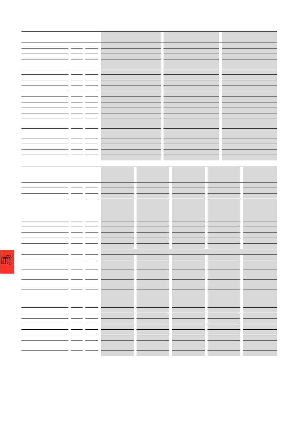
Remote I/OXI/ONGateways
XNE-GWBR-PBDP
XNE-GWBR-CANOPEN
XNE-GWBR-2ETH-IP
Gateways XNE
Fieldbus
PROFIBUS-DP
CANopen
Ethernet
Protocol
PROFIBUS-DPV0 and PROFIBUS-DPV1 CANopen
EtherNet-IP
Maximum number of stations
48
modules (XN, XNE) of slice design
or max. length of station: 1 m
62
modules (XN, XNE) of slice design
or max. length of station: 1 m
74
modules (XN, XNE) of slice design
or max. length of station: 1 m
System supply
U
SYS
V DC 24 V DC/5 V DC
24
V DC/5 V DC
24
V DC/5 V DC
Permissible range, 5 V DC
U
SYS
V DC 4.7 - 5.3
4.7 - 5.3
4.7 - 5.3
Permissible range, 24 V DC U
SYS
V DC 18 - 30
18 - 30
18 - 30
Field voltage
U
L
V DC 24
24
24
Permissible range
U
L
V DC 18 - 30
18 - 30
18 - 30
Ripple
%
< 5 (to EN 61131-2)
< 5 (to EN 61131-2)
< 5 (to EN 61131-2)
Servicing interface
PS/2 socket
PS/2 socket
Mini USB
Fieldbus terminals
Push-in spring-cage terminals
Push-in spring-cage terminals
2
x RJ45 socket
Transfer rate
kBit/s 9.6 - 12000
20, 50, 125, 250, 500, 800, 1000
10000, 100000
Data transfer
rate setting
Automatic
Through DIP switch
or automatically
Automatic
Address assignment
Through DIP switch
Through DIP switch
Through DIP switch,
BootP, DHCP or PGM
Fieldbus termination
Through DIP switch
Through DIP switch
-
Number of parameter bytes
2
-
-
Number of diagnosis bytes
2
-
-
Address range
1 - 125
decimal
1 - 63
decimal
1 - 254
decimal
XN-GWBR-PBDP XN-GWBR-
CANOPEN
XN-GWBR-DNET
XN-GWBR-
MODBUS-TCP
XN-PLC-
CANOPEN
Gateways XN with built-in supply module
Fieldbus
PROFIBUS-DP
CANopen
DeviceNet
Ethernet
CANopen
Protocol
PROFIBUS-DPV0
CANopen
DeviceNet
Modbus-TCP
CANopen
Maximum number of stations
74
modules
(
XN, XNE) of
slice design or
max. length of
station: 1 m
74
modules
(
XN, XNE) of
slice design or
max. length of
station: 1 m
74
modules
(
XN) of
slice design or
max. length of
station: 1 m
74
modules
(
XN, XNE) of
slice design or
max. length of
station: 1 m
74
modules
(
XN, XNE with limita-
tions) of slice design
or max. length of
station: 1 m
System supply
U
SYS
V DC 24 V DC/5 V DC
24
V DC/5 V DC
24
V DC/5 V DC
24
V DC/5 V DC
24
V DC/5 V DC
Permissible range, 5 V DC
U
SYS
V DC 4.7 - 5.3
4.7 - 5.3
4.7 - 5.3
4.7 - 5.3
4.7 - 5.3
Permissible range, 24 V DC U
SYS
V DC 18 - 30
18 - 30
18 - 30
18 - 30
18 - 30
Field voltage
U
L
24
24
24
24
24
Permissible range
U
L
V DC 18 - 30
18 - 30
18 - 30
18 - 30
18 - 30
Ripple
%
< 5 (to EN 61131-2)
Servicing interface
PS/2 socket
PS/2 socket
PS/2 socket
PS/2 socket
PS/2 socket
Fieldbus terminals
1
x D-sub 9-pin
socket
Open style
connector
Open style
connector
RJ45 bus
Open style
connector
Transfer rate
kBit/s 9.6 - 12000
10, 20, 50, 125, 250,
500, 800, 1000
125, 250, 500
10000, 100000
10, 20, 50, 125, 250,
500, 800, 1000
Data transfer
rate setting
Through DIP switch Through DIP switch Automatic
Software
Address assignment
2
decimal
rotary coding
switches
2
decimal
rotary coding
switches
2
decimal
rotary coding
switches
Decimal rotary
coding switch,
BootP, DHCP or
I/Oassistant
Software
Fieldbus termination
External
External
External
External
Number of parameter bytes
5
Number of diagnosis bytes
3
Address range
1 - 99
decimal
1 - 99
decimal
1 - 63
decimal
1 - 254
decimal
1 - 127
decimal
Program data
kByte -
-
-
-
128
Program code
kByte -
-
-
-
128
Cycle time for 1 k of
instructions (bits, bytes)
ms
-
-
-
-
0.5
Real-time clock
-
-
-
-
Yes