


 55 / 439

Contactor combinations
Star-delta combination
2010
CA08103002Z-EN
www.eaton.com5/51
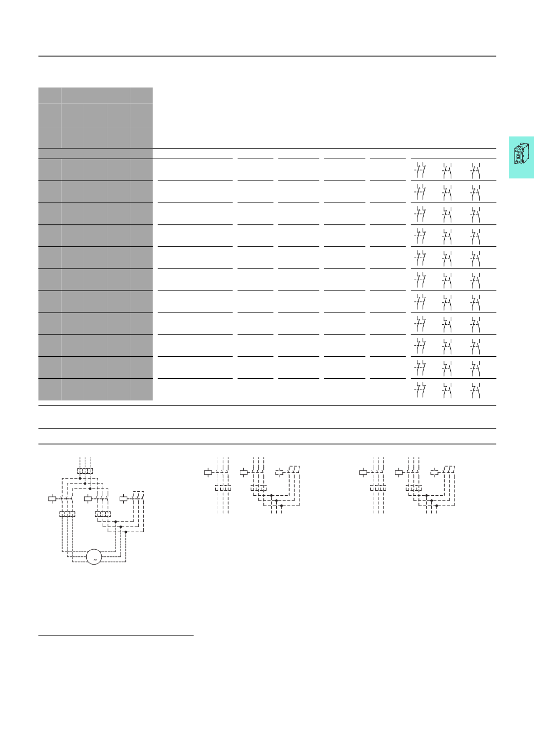
Components for self-assembly of star-delta combinations
Maximum operational rating of AC
motors 50 - 60 Hz
Individual components of the combination
Spare auxiliary contacts
AC-3
Changeover time
1)
Coil
to EN 50005
Switching element
to EN 50005 and EN 50012
230
V 400 V 500 V 690 V 1000 V
Mains
contactor
Q11
Delta
contactor
Q15
Star
contactor
Q13
Timing
relay
K1
Q11
Q15
Q13
kW kW kW kW kW up to
12
s
up to
20
s
up to
30
s
Part no. DIL Part no. DIL Part no. DIL Part no.
90
160 200 250 132
● ● ● M185A/22 M185A/22
M115/22
ETR4-51
110 200 250 315 160
● ● –
M225A/22 M225A/22
M150/22
ETR4-51
132 250 315 400 200
● ● ● M250/22
M250/22
M185A/22
ETR4-51
160 300 355 450 200
● ● ● M300A/22 M300A/22
M185A/22
ETR4-51
200 355 450 560 220
● ● –
M400/22
M400/22
M250/22
ETR4-51
250 450 560 600 220
● ● ● M500/22
M500/22
M300A/22
ETR4-51
300 560 710 900 355
● ● ● M580/22
M580/22
M400/22
ETR4-51
350 630 750 950 355
● ● ● M650/22
M650/22
M400/22
ETR4-51
400 710 900 1200 1400
● ● ● M750/22
M750/22
M580/22
ETR4-51
450 800 950 1300 1400
● ● ● M820/22
M820/22
M580/22
ETR4-51
560 1000 1200 1700 1700
● ● –
M1000/22 M1000/22
M650/22
ETR4-51
Notes
1)
Longer changeover times please enquire
Components for self-assembly
Notes
Overload relay settings
Timing relay set to approx. 10 s
Main circuit:
I
N
Starting
Depending on the coordination type required (i.e.
Type “1” or Type “2”) it must be established whether
the fuse protection and the input wiring for the
mains contactor and delta contactor are to be
common or separate.
A
x 0.58
Motor protection in Y and △ positions
≦ 15 s
B
x 1
In Y position only limited motor protec-
tion
15 – 40
s
Control circuit:
If the combinations are to be used within the scope
of IEC/EN 60 204 Part 1, VDE 0113 Part 1, then Point
9.1.1
regarding the supply of control circuits, must
be observed.
C
x 0.58
Motor not protected in Y position
> 40 s
21
22
31
32
31
32
43
44
31
32
43
44
21
22
31
32
31
32
43
44
31
32
43
44
21
22
31
32
31
32
43
44
31
32
43
44
21
22
31
32
31
32
43
44
31
32
43
44
21
22
31
32
31
32
43
44
31
32
43
44
21
22
31
32
31
32
43
44
31
32
43
44
21
22
31
32
31
32
43
44
31
32
43
44
21
22
31
32
31
32
43
44
31
32
43
44
21
22
31
32
31
32
43
44
31
32
43
44
21
22
31
32
31
32
43
44
31
32
43
44
21
22
31
32
31
32
43
44
31
32
43
44
Q11
1 3 5
642
Q15
1 3 5
642
Q13
1 3 5
642
U1
V1
W1
M1
3
M1
V2
W2
U2
A
C
B
Q11
1
2
3
4
5
6
Q15
1
2
3
4
5
6
Q13
1 3 5
6 42
C
A
Q11
1
2
3
4
5
6
Q15
1
2
3
4
5
6
Q13
1 3 5
6 42
C
A
SDAINL