


 54 / 439

5/50
Contactor combinations
Star-delta combinations
2010
CA08103002Z-EN
www.eaton.comEngineering
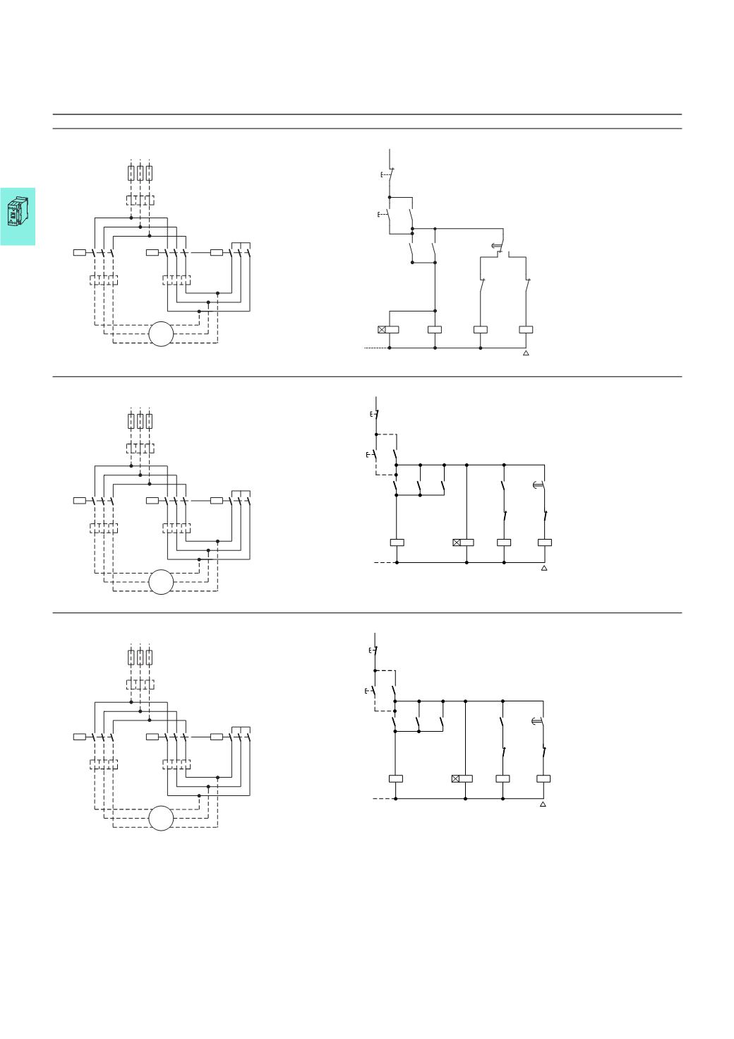
Circuit diagrams, Star-delta combinations
SDAINLEM
SDAINLM12…SDAINLM55
SDAINLM70…SDAINLM260
Overload relay settings
Starting
A
:
I
N
x 0.58
Motor protected in Y and △- positions
F 15 s
B
:
I
N
x 1
Only partial motor protection in Y position
15 – 40
s
C
:
I
N
x 0.58
Motor not protected in Y position
> 40 s
Timing relay set to approx. 10 s
Main circuit:
Depending on the type of coordination required (i.e. Type “1” or Type “2”) it must be established whether the fuse protection and the input wiring for the mains
contactor and delta contactor are to be common or separate.
L1 L2 L3
F1
M1
Q13
0.58
x
I
n
0.58
x
I
n
3
~
M
C
A
Q15
Q11
V1
U1
W1
W2
V2
U2
1 3 5
2 4 6
1 3 5
2 4 6
1 3 5
2 4 6
B
1
x
I
n
0
21
22
I
13
Q11
14
14
13
44
Q11
Q13
43
14
13
15
K1
Q15
22
21
Q13
22
21
N
N
16 18
Q11
Q15
Y
A2
A1
A2
A1
K1
A2
A1
Q13
A2
A1
L1 L2 L3
F1
M1
Q13
0.58
x
I
n
0.58
x
I
n
3
~
M
C
A
Q15
Q11
V1
U1
W1
W2
V2
U2
1 3 5
2 4 6
1 3 5
2 4 6
1 3 5
2 4 6
B
1
x
I
n
S11
0
(–)
N
Q11
Q13
Q13
Q15
K1
I
Q11
Q11
Q15
Q13
K1
Q15
N
Y
K1
21
22
13
14
A2
A1
A2
A1
53
54
22
21
28
17
17
18
14
13
53
54
53
54
A2
A1
A2
A1
22
21
L1 L2 L3
F1
M1
Q13
0.58
x
I
n
0.58
x
I
n
3
~
M
C
A
Q15
Q11
V1
U1
W1
W2
V2
U2
1 3 5
2 4 6
1 3 5
2 4 6
1 3 5
2 4 6
B
1
x
I
n
S11
0
(–)
N
Q11
Q13
Q13
Q15
K1
I
Q11
Q11
Q15
Q13
K1
Q15
N
Y
K1
21
22
13
14
A2
A1
A2
A1
13
14
22
21
28
17
17
18
14
13
13
14
43
44
A2
A1
A2
A1
22
21
SDAINL