


 308 / 336

16/10
Total Solution to Earthing & Lightning Protection |
9AKK106354A3360
16
Technical reference
IEC/BS EN 62305-3 - Physical damage to structures & life hazard
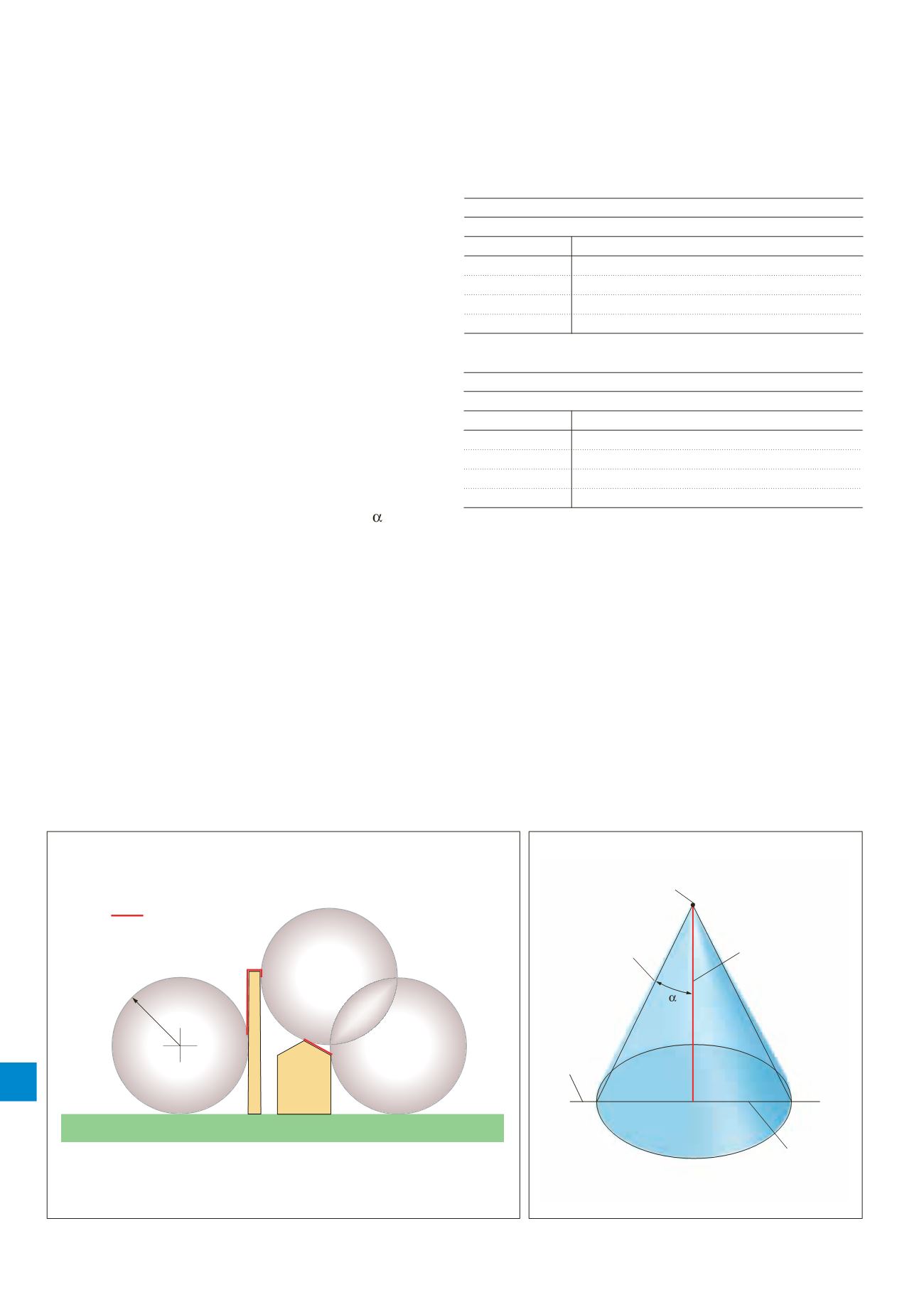
The rolling sphere method
The rolling sphere method is a simple means of identifying
areas of a structure that need protection, taking into account
the possibility of side strikes to the structure. The basic
concept of applying the rolling sphere to a structure is
illustrated in Figure 6.
The rolling sphere method was used in BS 6651, the only
difference being that in IEC/BS EN 62305 there are different
radii of the rolling sphere that correspond to the relevant
class of LPS (see Table 8).This method is suitable for defining
zones of protection for all types of structures, particularly
those of complex geometry.
The protective angle method
The protective angle method is a mathematical simplification
of the rolling sphere method. The protective angle ( ) is the
angle created between the tip (A) of the vertical rod and
a line projected down to the surface on which the rod sits
(see Figure 7).
The protective angle afforded by an air rod is clearly a three
dimensional concept whereby the rod is assigned a cone
of protection by sweeping the line AC at the angle of
protection a full 360º around the air rod.
The protective angle differs with varying height of the air rod
and class of LPS. The protective angle afforded by an air rod is
determined from Table 2 of IEC/BS EN 62305-3 (see Figure 9).
Varying the protection angle is a change to the simple 45º
zone of protection afforded in most cases in BS 6651.
Furthermore the new standard uses the height of the air
termination system above the reference plane, whether that
be ground or roof level (See Figure 8).
The protective angle method is better suited for simple
shaped buildings. However this method is only valid up to
a height equal to the rolling sphere radius of the
appropriate LPL.
Table 8:
Max. values of rolling sphere radius corresponding to the Class of LPS
Class of LPS
Rolling sphere radius
I
20 m
II
30 m
III
45 m
IV
60 m
Table 9:
Max. values of mesh size corresponding to the Class of LPS
Class of LPS
Mesh size
I
5 x 5 m
II
10 x 10 m
III
15 x 15 m
IV
20 x 20 m
Tip of air termination
Reference
plane
Protective
angle
Radius of
protected area
Height of an air
termination rod
above the reference
plane of the area
to be protected
h
A
C
Figure 7. The protective angle method for a single air rod
Figure 6. Application of the rolling sphere method
Rolling
sphere
radius
Air termination
required