
14/10
Total Solution to Earthing & Lightning Protection |
9AKK106354A3360
14
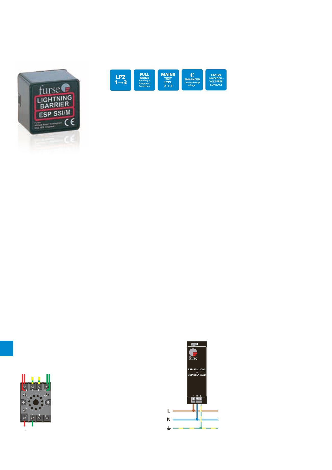
Combined Category C, B tested data link protector and Combined Type 2
and Type 3 tested mains protector (to BS EN 61643) suitable for Solid State
Interlocking (SSI) mains power and data links. Protectors are Network Rail
approved. For use on lines running within buildings at boundaries up to LPZ 1
through to LPZ 3 to protect sensitive electronic equipment.
Specific systems protection
ESP SSI Series
Installation
ESP SSI/B:
Connect in series with the data link either
near where it enters the trackside location cabinet or the
equipment room.
ESP SSI/120AC and ESP SSI/140AC:
Install in parallel,
within the trackside cabinet or equipment room. The protector
should be installed on the load side of the fuses, at the
secondary side of the step-down transformer. Connect, with
very short leads, to phase (BX), neutral (NX or CNX) and earth.
Full product range order codes can be found on pages 17/8-17/9
Parallel connection of single phase
protectors ESP SSI/120AC and ESP
SSI/140AC (fuses not shown for clarity)
1 - Earth in Line
2 - Primary signal in + Line
3 - Secondary signal in + Line
4 - Not connected
5 - Signal out + (to DLM) Clean
6 - Signal out - (to DLM) Clean
7 - Not connected
8 - 100 Ω terminating Clean resistor
9 - Primary signal in - Line
10 - Secondary signal in - Line
11 - Earth in Line
Signal In
Signal In
Earth
Signal Out
Terminating
resistor
Application
To prevent transient overvoltage damage to Solid State Interlocking
(SSI) systems, protectors should be fitted in trackside cabinets and
equipment rooms, on both the data link and the mains power lines.
–– For single phase mains power supplies of 90-150 Volts,
use the ESP SSI/120AC (formerly ESP 120X)
–– For single phase mains power supplies of 90-165 Volts,
use the ESP SSI/140AC (formerly S065)
–– For SSI data links, use the ESP SSI/B (or ESP SSI/B/G)
base unit with the ESP SSI/M protection module
Use ESP PTE002 SSI tester for line-side testing of
SSI/M modules.
Features & benefits
–– Accepted for use on Network Rail infrastructure. NRS
PADS references: ESP SSI/M - 086/047066;
ESP SSI/B - 086/047067; ESP SSI/120AC - 086/047058
and ESP SSI/140AC - 086/047059 (Network Rail Approval
PA05/00471)
–– Very low let-through voltage (enhanced protection to
IEC/BS EN 62305) between all sets of conductors - Full
Mode protection (ESP SSI/120AC and ESP SSI/140AC) and
all signal lines (ESP SSI/M)
–– ESP SSI/B (or ESP SSI/B/G) modified base can be
permanently wired into the system
–– ESP SSI/M plug-in protection module can be replaced
without interfering with the operation of the system
–– ESP SSI/B (or ESP SSI/B/G) incorporates a 100 Ω
terminating resistance that can be connected if required
–– ESP SSI/B (or ESP SSI/B/G) can be flat mounted, or a
built-in DIN rail foot allows simple clip-on mounting to
top-hat (ESP SSI/B) or G DIN rails (ESP SSI/B/G)
–– ESP SSI/120AC and ESP SSI/140AC are a compact size
for easy installation in trackside cabinets and control rooms
–– ESP SSI/120AC and ESP SSI/140AC have three way
visual indication of protector status and advanced
pre-failure warning


