


 86 / 413

4/20
Presentation
The
TSXCTY2C
measurement and counter module is used with fast machines requiring
precisemeasurements with short cycle times and high input frequencies (woodworking
machines, packingmachines, etc.).
The
TSX CTY 2C
measurement and counter module provides the standard functions
(
speed monitoring, reflex outputs, etc.) for performing a simple position control
function, by the application program.
The
TSX CTY 2C
measurement and counter module also enables special functions
to be managed.
Description
The front panel of the
TSX CTY 2C
measurement and counter module comprises:
1
One 15-way SUB-D connector per channel for connecting:
v
Counter sensors or incremental encoder
v
SSI absolute encoder or parallel output encoder with Modicon Telefast
ABE 7CPA11
sub-base
v
Sensor power supply
v
Encoder power supply feedback for checking that it is supplied correctly
2
One 20-way HE10 connector for connecting the following for each channel:
v
Auxiliary inputs: preset, enable and capture
v
Reflex outputs
v
Programmable frequency output
v
Power supplies for auxiliary I/O and encoders
3
Rigid casing, which:
v
Holds the electronic card
v
Locates and locks the module in its slot
4
Module diagnostic LEDs:
v
Module diagnostics:
-
Green RUN LED, module operating
-
Red ERR LED, internal fault, module failure
-
Red I/O LED, external fault
v
Channel diagnostics:
-
Green CH
p
LED: channel diagnostics available
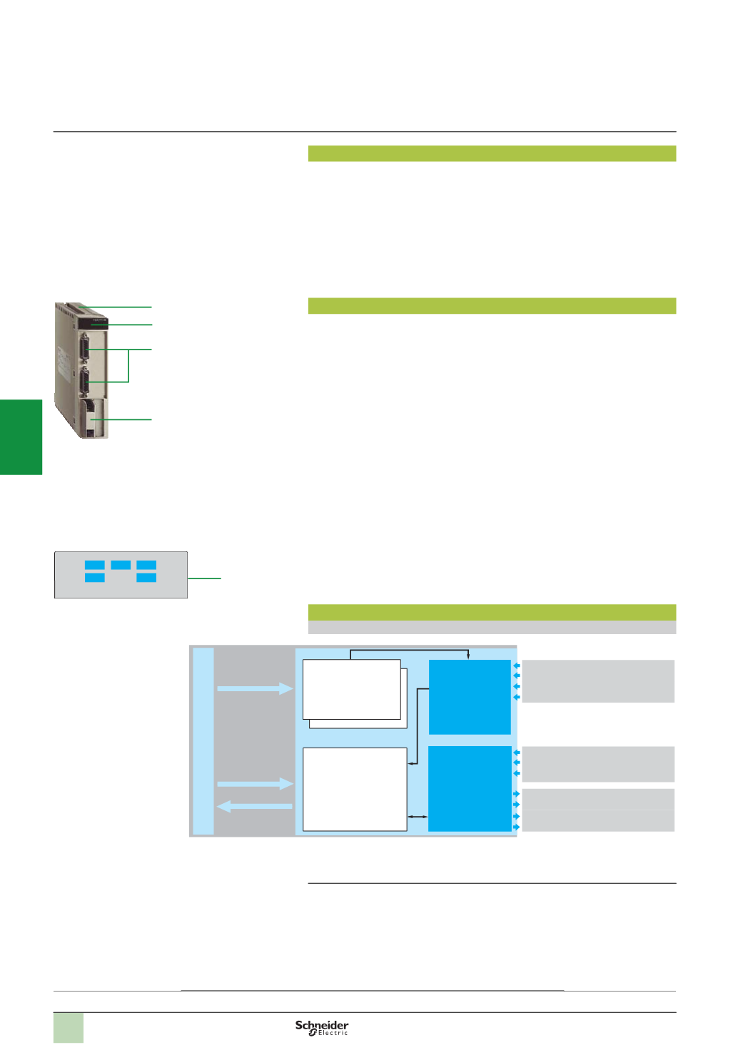
Operation block diagram
Block diagram of a channel
Counter modules are set up using Unity Pro or PL7 Junior/Pro software
(1)
The enable input and output 2 cannot be used simultaneously.
Presentation,
description,
operation
4
ERR
CH0 RUN
CH1
I/O
Modicon Premiumautomation
platform
TSX CTY 2C measurement and counter module
3
4
1
4
TSX CTY 2C
Configuration
and adjustment
%
KW, %MW
%
Q, %QW
%
I, %IW
Configuration
parameters
Discrete sensor or
incremental
encoder or SSI
absolute encoder
signals
Auxiliary I/O
processing
Enable input
(1)
Capture input
Preset input
Reflex output 0
Reflex output 1
Output 2
(1)
Programmable frequency output 3
Up/down counting function
and measurement with
processing:
-
Measurement
comparison with 2
thresholds
-
Event management
-
Speed monitoring
Incremental encoder input
Sensor inputs
SSI absolute encoder inputs
ABE 7CPA11 inputs
Architectures:
page 4/21
References:
pages 4/22 ...
2
1
3
4
5
6
7
8
9
10