


 83 / 413

4/17
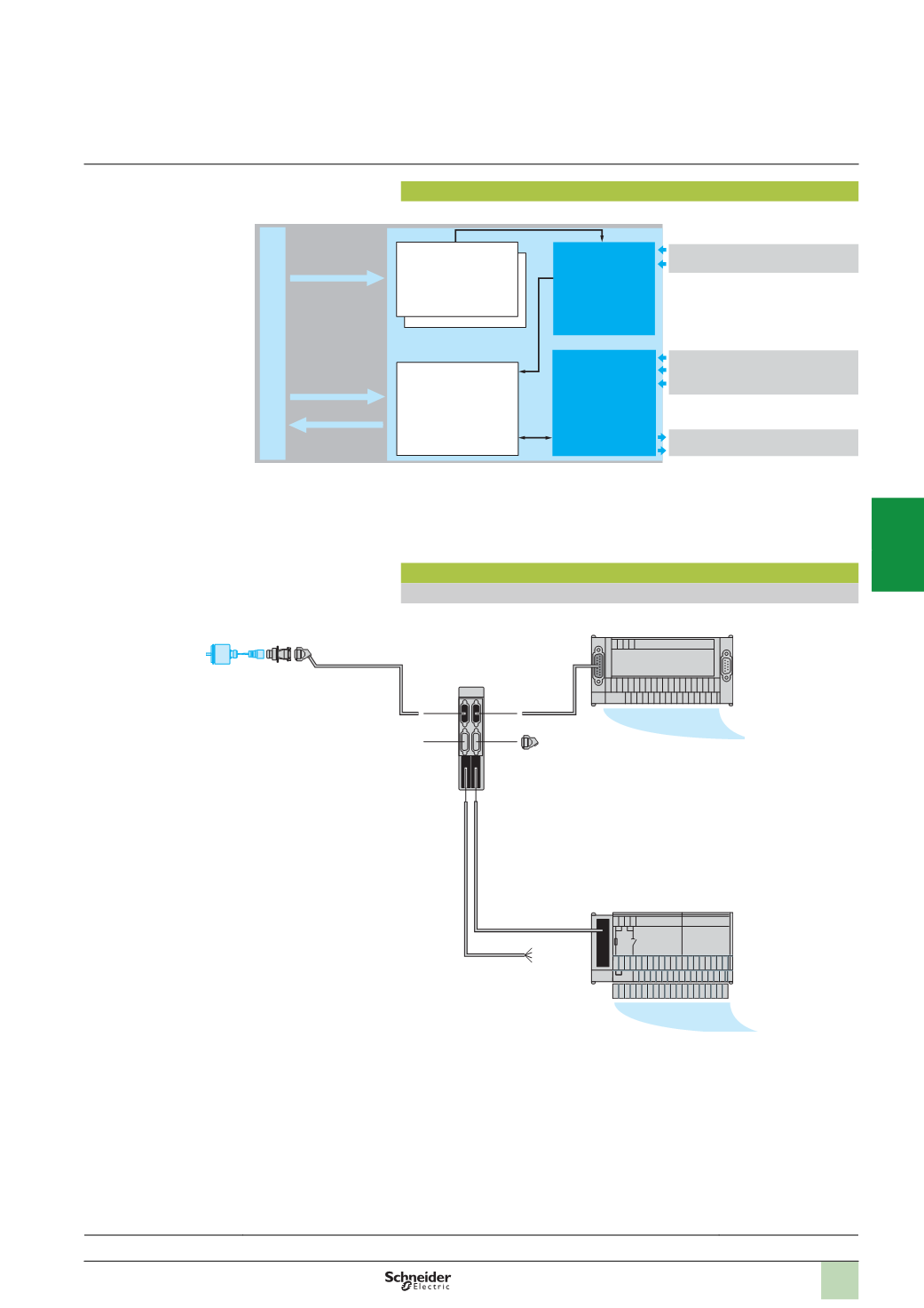
Operation block diagram
Block diagram of a channel
Counter modules are set up using Unity Pro or PL7 Junior/Pro software.
Architectures
Example of an architecture with counter inputs
Upcounting and/or
downcounting function
with processing:
-
Measurement
comparison with 2
thresholdsand2setpoints
-
Event management
Configuration
parameters
Configuration
and adjustment
%
KW, %MW
%
Q, %QW
%
I, %IW
Discrete sensor
or incremental
encoder signals
Auxiliary I/O
processing
ÐÐ++
GND
2
4
6
8
10
12
14
16
18
20
22
24
26
28
30
32
1
3
5
7
9
11
13
15
17
19
21
23
25
27
29
31
Modicon Telefast
Ð
++
Ð
1
2
3
4
100
101
102
103
104
105
106
107
108
109
110
111
112
113
114
115
C
C
C
C
300
301
302
303
304
305
306
307
308
309
310
311
312
313
314
315
200
201
202
203
204
205
206
207
208
209
210
211
212
213
214
215
Modicon Telefast
4
5
6
1
2
3
3
TSX CTY 4A
ABE 7CPA01
ABE 7H16R20
+ ABE 7BV20
1
Incremental encoder
2
TSX TAP S15 05
/
24
connector
3
TSX CCP S15
cable with connectors
4
TSX CAP S15
connector
5
TSX CDP
pp
1
preformed cable with connectors
6
TSX CDP
pp
2
or
TSX CDP
pp
3
rolled ribbon cable or cable with connectors
Operation,
architectures
Modicon Premiumautomation
platform
TSX CTY 2A/4A counter modules
Presentation:
page 4/16
References:
pages 4/18 ...
Sensor inputs
Counter enable input
Incremental encoder input
Capture input
Preset input
Reflex output 0
Reflex output 1
Channels
0
and 1
Channels
2
and 3
Channel 2
Sensor inputs
Channel 0
Auxiliary inputs
Reflex outputs
Channels 0 and 1
Channel 3
Channel 0
Channel 1
2
1
3
4
5
6
7
8
9
10