


 71 / 413

4/5
Modicon Premium automation
platform
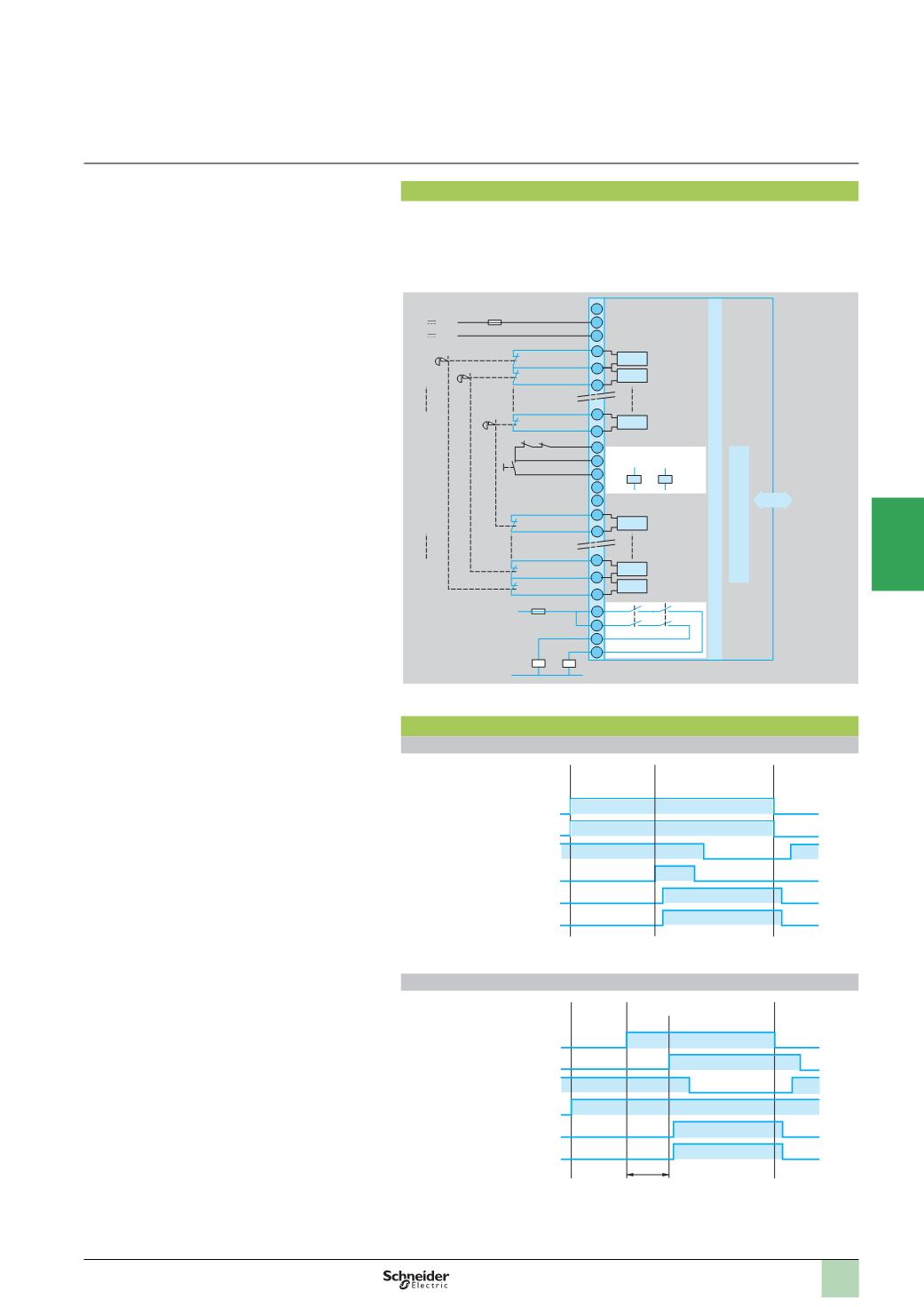
Preventa safety module type TSX PAY 262
Function
(
continued)
13-14
and 23-24
Y1-Y2/S33:
Y2/S33-S34:
Y3-Y4:
S121 to S232:
S01 to S112:
A1-A2:
B1:
Safety outputs, volt-free
Feedback loop
Run enable
Choice of reactivation mode
12
contacts on (+) input channel
12
contacts on (+) input channel
c
24
V external power supply
Selection of double or single contact wiring
TSX PAY 262 module schematic
To ensure the safety function irrespective of the first failure, it is compulsory to use:
b
For the inputs: Emergency stop pushbuttons or safety limit switches with double
contacts
b
For the outputs: if relaying is necessary, use a guided contact relay
b
On the module power supply : an F1 protection fuse.
Functional diagrams
Emergency stop function
Input channel (+) S121 to S232
Input channel (-) S01 to S112
Feedback loop Y1-Y2/S33
Start-up button Y2/S33-S34 N/O
Output 13-14 N/O
Output 23-24 N/O
Protective function with automatic start-up
Input channel (+) S121 to S232
Input channel (-) S01 to S112
Feedback loop Y1-Y2/S33
Shunt to Y2/S33-S34 N/O
Output 13-14 N/O
Output 23-24 N/O
K3
F1
S12
S13
S23
S11
S0
S1
Ix,23
Ix,11
Ix,0
S112
Y4
Y3
S34
Y2/S33
Y1
S111/S102
S11/S02
S01
S121
S131/S122
S141/S132
S231/S222
S232
23
13
14
24
B1
A2
A1
K4
K3
N(-)
24
V
0
V
K4
K2 K1
K2 K1
F2
L1(+)
TSX PAY 262
Ix,1
S21/S12
Ix,12
Ix,13
Bus
Safety logic
Bus interface
I
s
o
l
a
t
i
o
n
0
1
Power supply
voltage
On
Emergency stop not activated
Emergency stop
activated
0
1
200
ms
max.
1
st
switch
Power
supply
voltage
2
nd
switch
Guard closed
Guard open
1
2
3
4
5
6
7
8
9
10