


 63 / 413

3/21
Presentation
(
continued)
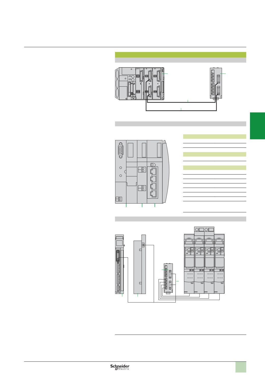
Control/command
HE 10 connection
Connection on bus using Modicon STB
(1)
Configuration example
(
for motor starter applications only):
Power supply module
Module
STB PDT 3100
Connection base
STB XBA 2200
Terminal block
STB XTB 1130
Parallel interface module
(2)
Module
STB EPI 2145
Connection base
STB XBA 3000
Network interface module
(3)
CANopen
STB NCO 1010
(4)
Fipio
STB NFP 2210
Ethernet TCP/IP
STB NIP 2210
InterBus
STB NIB 1010
(4)
Profibus DP
STB NDP 1010
(4)
DeviceNet
STB NDN 1010
(4)
Modbus Plus
STB NMP 2210
Terminal block
STB WTS 2120
TeSys Quickfit LAD 9AP3
pp
used with APP1 C
pp
modules
The motor starter is connected to an
APP 1C
p
7
module using an adaptor plate
APP 2CX
8
and a cable
APP 2AH40H060
10
.
Information is available on the module for each motor starter:
b
1
output: motor control
b
2
inputs: circuit-breaker status and contactor status
(1)
Please consult the “IP 20 distributed inputs/outputs Modicon” catalogue.
(2)
For 4 direct or 2 reversing motor starters.
(3)
Reference to be selected according to the network used.
(4)
Optimized version.
1
Automation platform
2
Connection cable
TSXCDP
pp
or
ABFH20
pp
3
Splitter box
LU9 G02
1
3
2
2
4
5
6
9
10
7
8
7
TeSys Quickfit module
8
Adaptor plate
APP 2CX
9
Splitter box
LU9 G02
for 8
direct motor starters with channel
connections on the
APP 1C
module side via
2
HE 10 connectors (20-way), and on the
TeSys Quickfit side via 8 RJ45 connectors
10
Connection cable
APP 2AH40H060
Installation system
TeSys Quickfit for motor starter
components
Components with spring terminals
4
Network interface module
5
Power supply module
6
Parallel interface module
2
1
3
4
5
6
7
8
9
10