


 37 / 413

2/9
Description,
functions
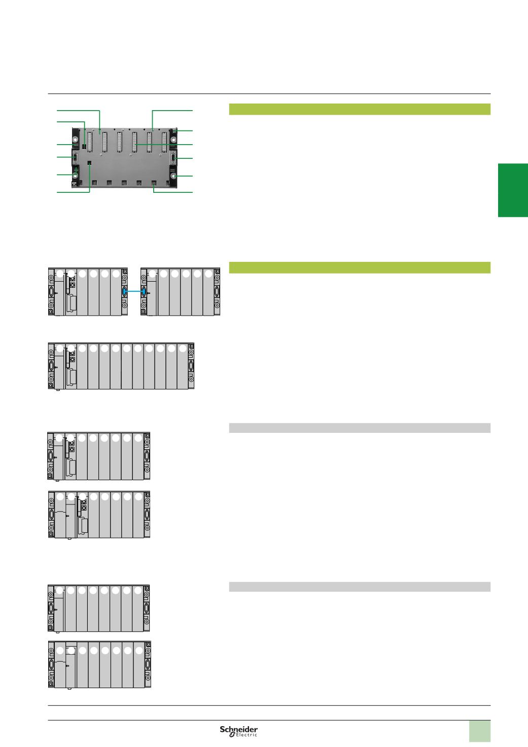
Description
TSX RKY
ppp
EX
racks comprise:
1
Ametal frame
2
Slots for anchoring the module pins
3
48-
way female 1/2 DIN connectors for module/rack connections (the first
connector is reserved for the power supply module)
4
A locating slot for the power supply module
5
Tapped holes for mounting the module
6
Four holes for mounting the rack
7
Slot for the rack address label
8
Slot for the station network address label
9
Two earth terminals for earthing the rack
10
Microswitches for coding the rack address (on extendable racks)
11
Two 9-way female SUB-D connectors for the remote connection of bus X, each
one to another rack
Rack addresses
Address 0:
this address is always assigned to the rack which holds the processor.
This rack can be located in any position on the line.
Addresses 1 to 7:
these can be assigned in any order to all the other extendable
racks of the station.
As the two racks with 4, 6, or 8 slots which make up each pair have the same
address on the bus X, position numbers are defined as follows:
b
Rack n “less-significant”: position 00 to xx (02, 04 or 06); rack n “most-significant”:
position 08 to yy (10, 12 or 14).
b
Racks with 12 slots each occupy an address (with position 00 to 10).
Installing the various modules on the standard or extendable rack with address 0
The rack with address 0 must contain a power supply module and the processor
module. For Premium PLCs which have two types of power supply (standard or
double-format), the position of the processor (standard or double-format) will depend
on the type of power supply used:
b
Using a standard format power supply module:
v
The power supply module systematically occupies position
PS
.
v
The processor module must be installed in positions
00
/
01
(
00
with standard
format processor).
v
The other modules are installed from position
02
(
01
with standard format
processor).
b
Using a double-format power supply module:
v
The power supply module systematically occupies positions
PS
and
00
.
v
The processor module must be installed in positions
01
/
02
(
01
with standard
format processor).
v
The other modules are installed from position
03
(
02
with standard format
processor).
Installing the various modules on extendable racks with addresses 1 to 7
Each rack must have either a standard format or double-format power supply
module:
b
Using a standard format power supply module:
v
The power supply module systematically occupies position
PS
.
v
The other modules are installed from position
00
onwards.
b
Using a double-format power supply module:
v
The power supply module systematically occupies positions
PS
and
00
.
v
The other modules are installed from position
01
onwards.
Primary rack address 0
with standard-format
power supply and
processor
Primary rack address 0
with double-format
power supply and
standard-format
processor
Extension rack
address n with
standard-format
power supply
Extension rack
address n with
double-format
power supply
Modicon Premium automation
platform
Multirack configuration without remote module
01
02 03 04
PS 00
09
10 11 12
PS 08
“
less-significant” “most significant”
Address rack n, example with two 6-slot racks, standard format
power supply and standard format processor
01
02 03 04
PS 00
07
8 9 10
05 06
Address rack n, example with one 12-slot rack, standard format
power supply and standard format processor
1
10
8
11
7
4
5
9
3
11
6
2
01
02 03 04 05 06
PS 00
01 02 03 04 05 06
PS 00
02
03 04 05 06
01
PS 00
01
02 03 04 05 06
PS 00
Presentation:
page 2/8
References:
pages 2/10 ...
2
1
3
4
5
6
7
8
9
10