


 333 / 356

D-85
Thermal management
of switchboards
Heating
D-85
Additional informations
Switchboard heating
The heating resistor, placed in the bottom of the switchboard, maintains the internal
temperature 10 °C higher than the external temperature. When the switchboard is
not in operation, the heater compensates the dissipated power normally emitted by
the switchboard.
The power of the heating resistor is calculated:
using the equation: Pr = (
D
T x S x K)
- P
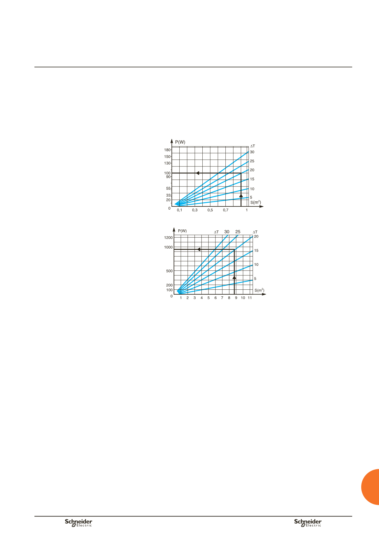
or using the charts below, based on the exposed surface area of the enclosure and
the desired difference in temperature.
Chart to determine the heating resistor for small wall-mount enclosures
(exposed surfaces
y
1 m
2
)
b
b
DD381788
Chart to determine the heating resistor for all types of enclosures and cubicles
DD381789
Calculation data
P :
power dissipated by the devices, connections and busbars (in Watts)
P
r
:
power of the heating resistor (in Watts)
T
m
:
maximum internal temperature in the device zone (in °C)
T
i
:
average internal temperature (in °C)
T
e
:
average external temperature (in °C)
D
T
m
= T
m
–
T
e
D
T
= T
i
–
T
e
S :
total free surface area of the enclosure (expressed in m
2
)
K :
thermal-conduction coefficient of the material (W/m
2
°C)
K = 5.5 W/m
2
°C for painted sheet metal
D:
ventilation throughput (in m
3
/h)
Note:
the dissipated power of each device is provided by the manufacturer.
Add approximately 30 % to account for the connections and the busbars.
Thermal characteristics of
switchboards