


 332 / 356

D-84
Switchboard ventilation
The air enters the lower section via the fans and exits the upper section:
through a ventilated roof
or through a ventilation opening.
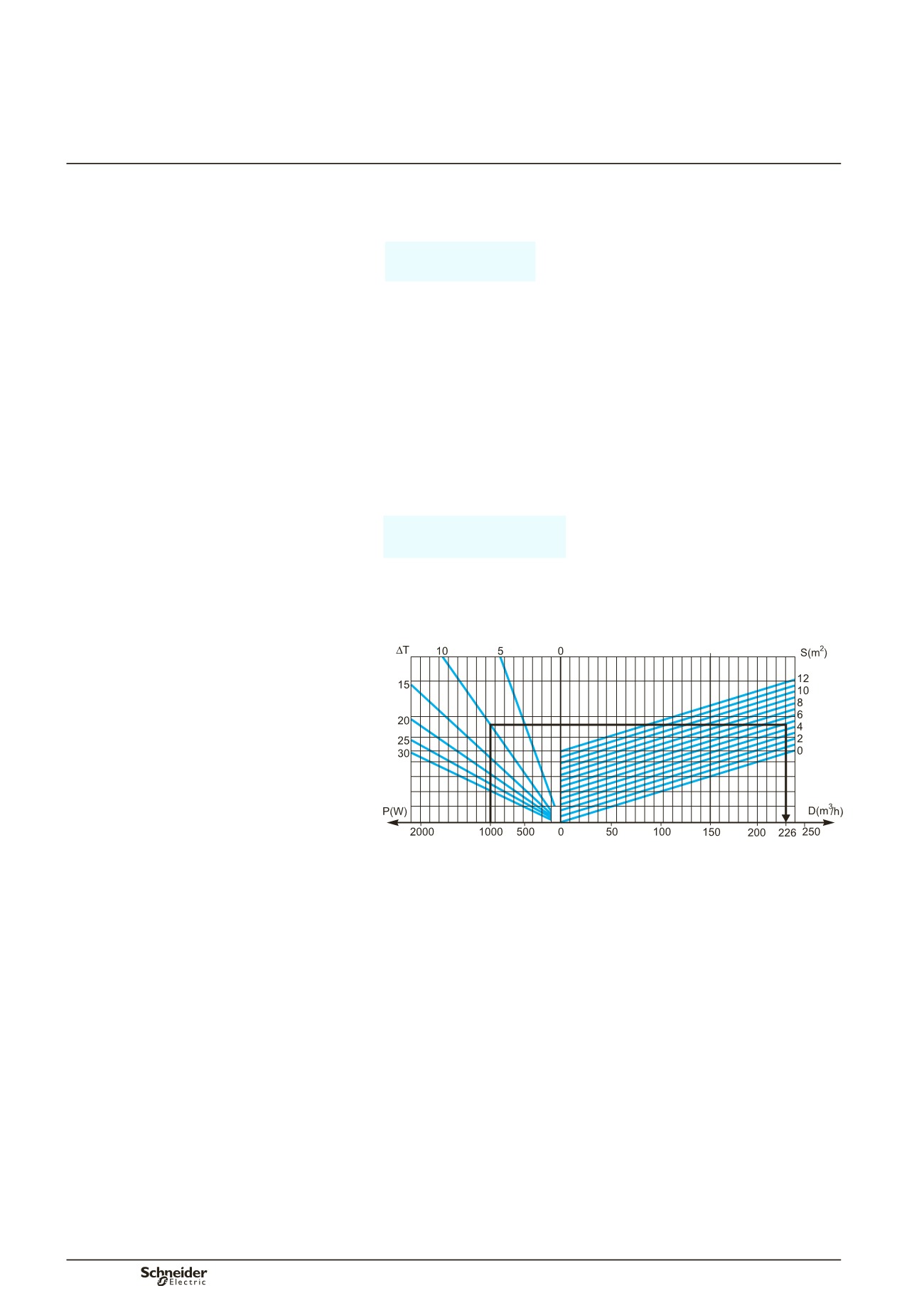
The air throughput of the fans is determined by the equation:
The chart below can be used to determine the necessary throughput, based on the
dissipated power, the difference in temperature (internal - external) and the exposed
surface area of the enclosure.
b
b
Example
Consider an IP3X cubicle, 650 mm wide and 400 mm deep, containing components
(devices, connections, busbars, etc.) dissipating 1000 W.
The ambient temperature around the cubicle is 50 °C.
Given that the average temperature at mid-height should not exceed 60 °C, the
difference in temperature
D
T is equal to 60 - 50 = 10 °C.
The exposed surface of the cubicle (non adjacent to a wall or other cubicle)
is 4.46 m².
(back = 1.3 m², front = 1.3 m², roof = 0.26 m², side panels = 1.6 m²).
What is the necessary throughput of the ventilation system?
The throughput can be calculated as:
D = 234 m
3
/h.
In the range of Prisma Plus accessories, select a system with a throughput
of 300 m
3
/h.
DD381391
Calculation data
P :
power dissipated by the devices, connections and busbars (in Watts)
P
r
:
power of the heating resistor (in Watts)
T
m
:
maximum internal temperature in the device zone (in °C)
T
i
:
average internal temperature (in °C)
T
e
:
average external temperature (in °C)
D
T
m
= T
m
–
T
e
D
T
= T
i
–
T
e
S :
total free surface area of the enclosure (expressed in m
2
)
K :
thermal-conduction coefficient of the material (W/m
2
°C)
K = 5.5 W/m
2
°C for painted sheet metal
D:
ventilation throughput (in m
3
/h)
Note:
the dissipated power of each device is provided by the manufacturer.
Add approximately 30 % to account for the connections and the busbars.
Thermal management
of switchboards
Ventilation
D 3 1
•
P
D
T---- KS
–
×
=
D 3 1
•
1000
10
--------- 5 5
•
4 46
•
×
–
×
=
Additional informations
Thermal characteristics of
switchboards