


 261 / 327

TECHNICAL INFORMATION
Technical information
0.0
0.5
1.0
1.5
2.0
2.5
3.0
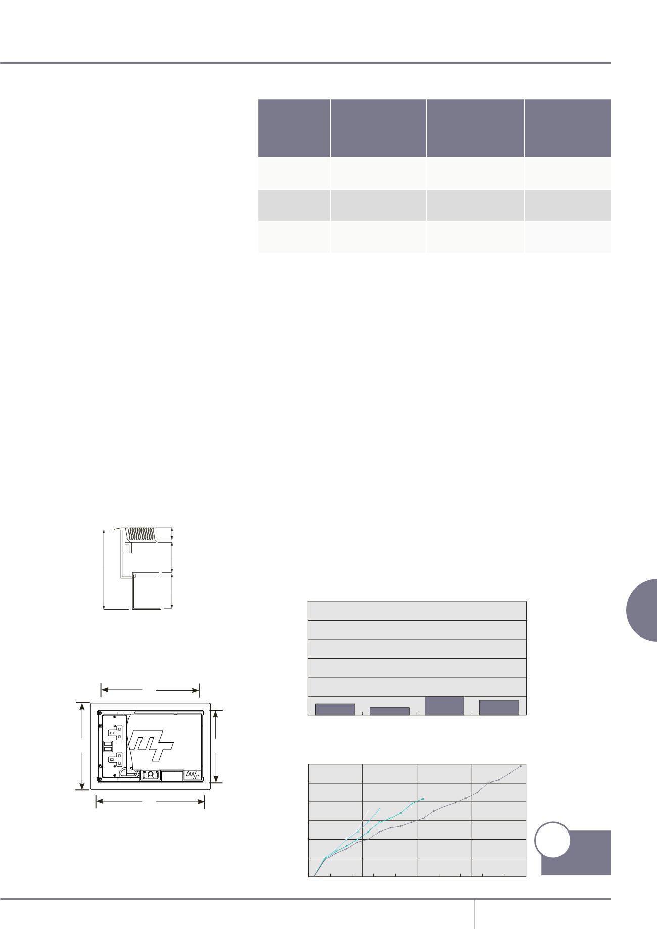
3mm maximum allowable permanent deflection
Point load without
Sub-frame
mm
Point load with
Sub-frame
Plate load without
Sub-frame
Plate load with
Sub-frame
Permanent Set
Underfloor to desk
| 261
Raised floor boxes
Three and four compartment boxes and a
range of grommets that can be configured
to meet client requirements for accessing
multiple services concealed below a raised
floor system.
Technical Specifications
Raised floor boxes are third party tested to
comply with:
BS EN 61534-22:2009
BS EN 60670-1:2005
BS EN 60670-23:2008
BS EN 50085-1:2005
BS EN 50085-2-2:2008
Material
• Lid/trim: flame retardant
polypropylene grey RAL 7011
• Box assembly: galvanised steel
• Load plate: 3mm zinc plated steel
• Accessory plate: galvanised steel
Installation
• Box module has 20 and 25mm
knockouts (pre-wired options available).
• Mounting plates:
3 compartment = 185 x 95mm
4 compartment = 185 x 71mm
• Standard accessory mounting plates
available depending on suitability of
floor box configuration.
• Cable covers protect cables when lid
is closed.
• Detailed installation instructions are
supplied in box.
Dimensions
No of
compartments
Nominal
trim size
(L1 x W1)
Cut out dimensions
(L2 x W2)
Accessory Plate
Dimensions
3
357 x 257mm
322 x 222mm
185 x 95mm
4
357 x 257mm
322 x 222mm
185 x 71mm
General tolerance
+3mm
Dimensions
• For dimensions of non standard boxes
and trims, contact Technical Hotline on
+44 (0)1424 856688.
Depth
of void
83mm
40mm
internal
35.6mm
6mm Flooring
Recess
W1
W2
L2
L1
0
0 100 200 300 400 500 600 700 800 900 1000
2
4
6
8
10
12
Load deflection for floor boxes with plate load
andwithout sub-frame
mm
kg
1/4 metric tonne 1/2 metric tonne
Plate load no
sub-frame
6mm maximum allowable
deflection point load
4mm maximum allowable
deflection point load
point load with
sub-frame
plate load with
sub-frame
BS EN 61534-22:2009
BS EN 50085-2-2:2008
point load no
sub-frame
3/4
metric tonne
Care should be taken to ensure that box edges are smoothed and free from burrs.
Carpet tile cut size for lid is 303 x 166mm
Load Testing
Load testing of floor boxes to:
BS EN 61534-22:2009
BS EN 50085-2-2:2008
The floor boxes have been tested to and
comply with the loading requirements of
the aforementioned standards.
There are two loading criteria for the floor
boxes:
1. A point loading; to simulate foot traffic or
light furniture like a chair leg / caster sitting
on the lid. The maximum permissible
deflection is 6mm (BS EN 61534-22:2009
and BS EN 50085-2-2:2008)
2. A plate loading; to simulate heavy foot
traffic or larger furniture loads. the
maximum permissible deflection is
4mm (BS EN 61534-22:2009) or 6mm
(BS EN 50085-2-2:2008)
Note:
The maximum permissible
permanent deflection after the load has
been removed is 3mm for both standards.
The loading graphs show the deflection
based on floor boxes without and with a
sub-frame. The point loading value is
approaching ¼ of a metric tonne without
sub-frame and reaching ¼ of a metric
tonne with sub-frame. In both cases the
permanent deflection is less than ¼ mm.
For plate loading without sub-frame the
value is approaching ¼ of a metric tonne
with 4mm deflection and ¼
of a metric
tonne with 6mm deflection. With the
sub-frame fitted the loading reaches ¼ of
a metric tonne with 4mm deflection and
½ a metric tonne with 6mm deflection. In
both cases the permanent deflection is
reaching 0.5mm.
Note:
floor boxes fitted with sub-frame
can exceed more than 1 metric tonne
plate load before lid failure. In all tests
(with and without sub-frame) the required
loading was reached without damage to
the plastic trim or compromised the lid.
3
p84
Product
Information