30
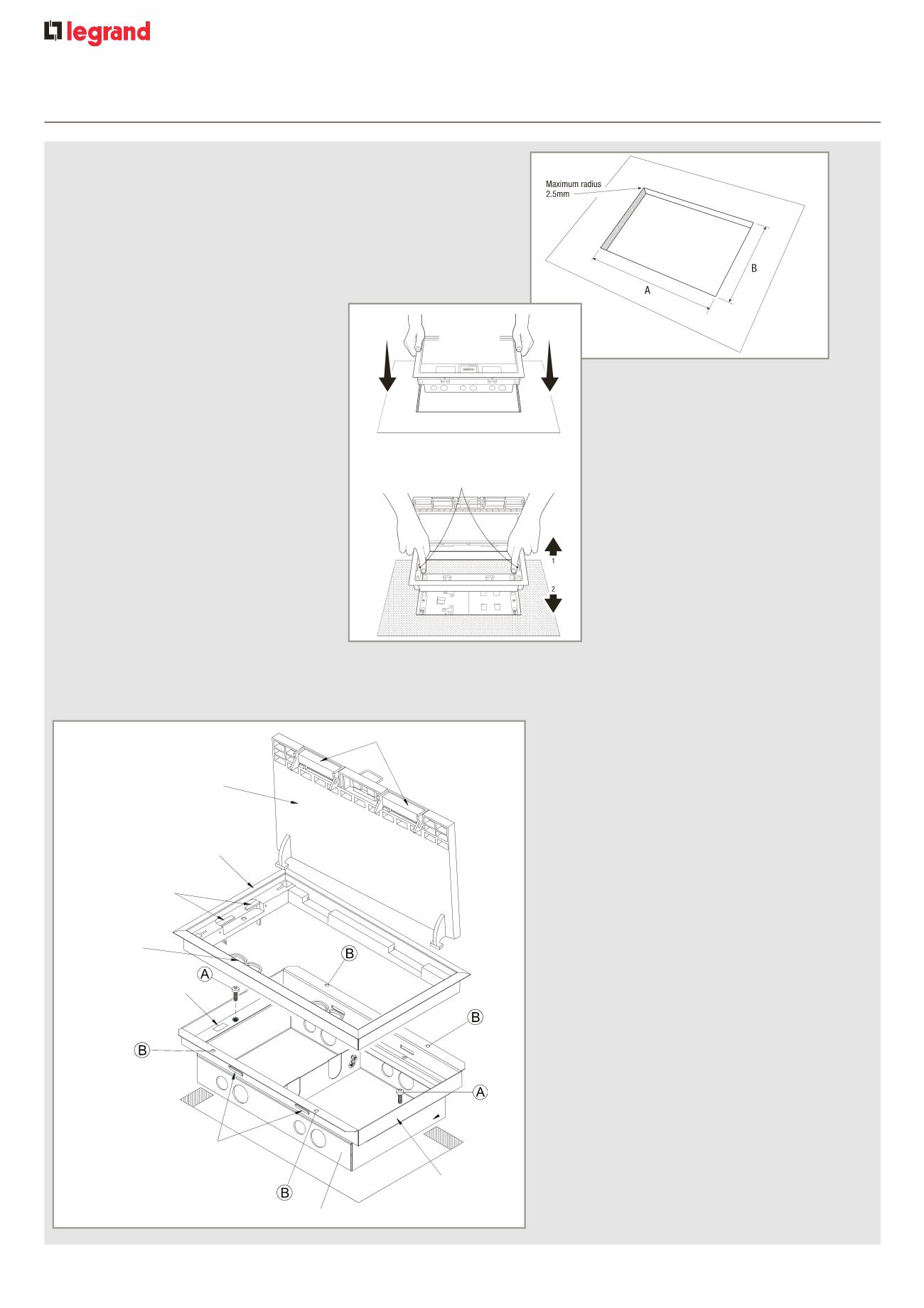
cavity floor service outlet boxes
installation
B) Box can be screw fitted to floor tile
by using holes (B) in mounting frame
(If hole in tile is outside maximum tolerance
Use 4 x No.8 25 mm self tapping screws)
A) Base can be detached from
mounting frame by releasing screws (A)
This enables the base to be connected to
the services and left under floor tiles for
protection until the carpet, lid and trim
are fitted
Cable routers can also be removed and
attached to opposite side of trim
Opening lid to an angle of 30° and lifting
upwards will detach lid from trim. Inserting
lid into the opposite side of trim will change
direction of the lid
1
Install box
This will engage the fixing latches
Fitting lid and trim
Lid and trim is a simple push fit
2
3
Lower base box into aperture and push
firmly down
1 The rachets allow the trim to find its own
level on top of the final floor finish
2 To remove, lift out by releasing the blue
locking handles
FOR SAFETY : All cables exiting boxes must be positioned into the cable routers on box trim and exit box via cable outlets
Lid and lid handle must always be placed in the closed positions
When using metal lid and trims, the lifting device at the centre of the lid is not to be used as a cable exit
PUSH
DOWN
Cut hole in floor tile
Minimum Maximum
Minimum Maximum
A
B
1 compartment
165 mm 167 mm
203 mm
205 mm
2 compartment
263 mm 265 mm
203 mm
205 mm
3 compartment
340 mm 342 mm
203 mm
205 mm
4 compartment
340 mm 342 mm
203 mm
205 mm
Tile ixing latch
Single base
Mounting frame
Trim
Trim locking
handles (blue)
Cable routers
Trim locking
handle grommet
Lid
Cable outlets


