


 94 / 210

94
In equipment containing control devices, the transformer
power depends on the maximum power required at a given
moment (inrush power), the permanent power, the voltage
drop and power factor
When determining the permissible instantaneous power (inrush power)
required, the following factors should always be taken into account :
• two inrush currents cannot occur at the same time
• power factor cos
ϕ
equals 0·5
• at maximum, 80% of devices are supplied at the same time (this
percentage can be calculated precisely for each device)
n
Determination of the inrush power
Where a simplified calculation of the power is required, the following
formula can be used :
P inrush = 0·8 (
Σ
Pm +
Σ
Pv + Pa)
Σ
Pm : sum of all contactor steady state power levels (holding power)
Σ
Pv : sum of all power levels of indicators and LEDs
1
Pa : inrush power of the largest contactor
Example :
A machine tool control cabinet comprising :
• 10 contactors for 4 kW motors, with a steady state power of 8 VA
• 2 contactors for 18·5 kW motor, with a steady state power of 20 VA
• 1 contactor for 45 kW motor, with a steady state power of 20 VA,
and an inrush power of 250 VA cos
ϕ
0·5
• 20 remote control relays, with a steady state power of 4 VA
• 30 signalling LEDs, with a consumption of 1 VA each
-
Σ
Pm = 220 VA { (10 x 8 VA) + (2 x 20 VA) + (1 x 20 VA) + (20 x 4 VA)}
-
Σ
Pv = 30 VA (30 x 1 VA)
- Pa = 250 VA
P inrush = 0·8 (220 + 30 + 250) = 400 VA at cos
ϕ
0·5
n
Determination of the rated power of a transformer
For control transformers, in particular, simply start with an inrush
power at cos
ϕ
0·5 and read the size from the table below
n
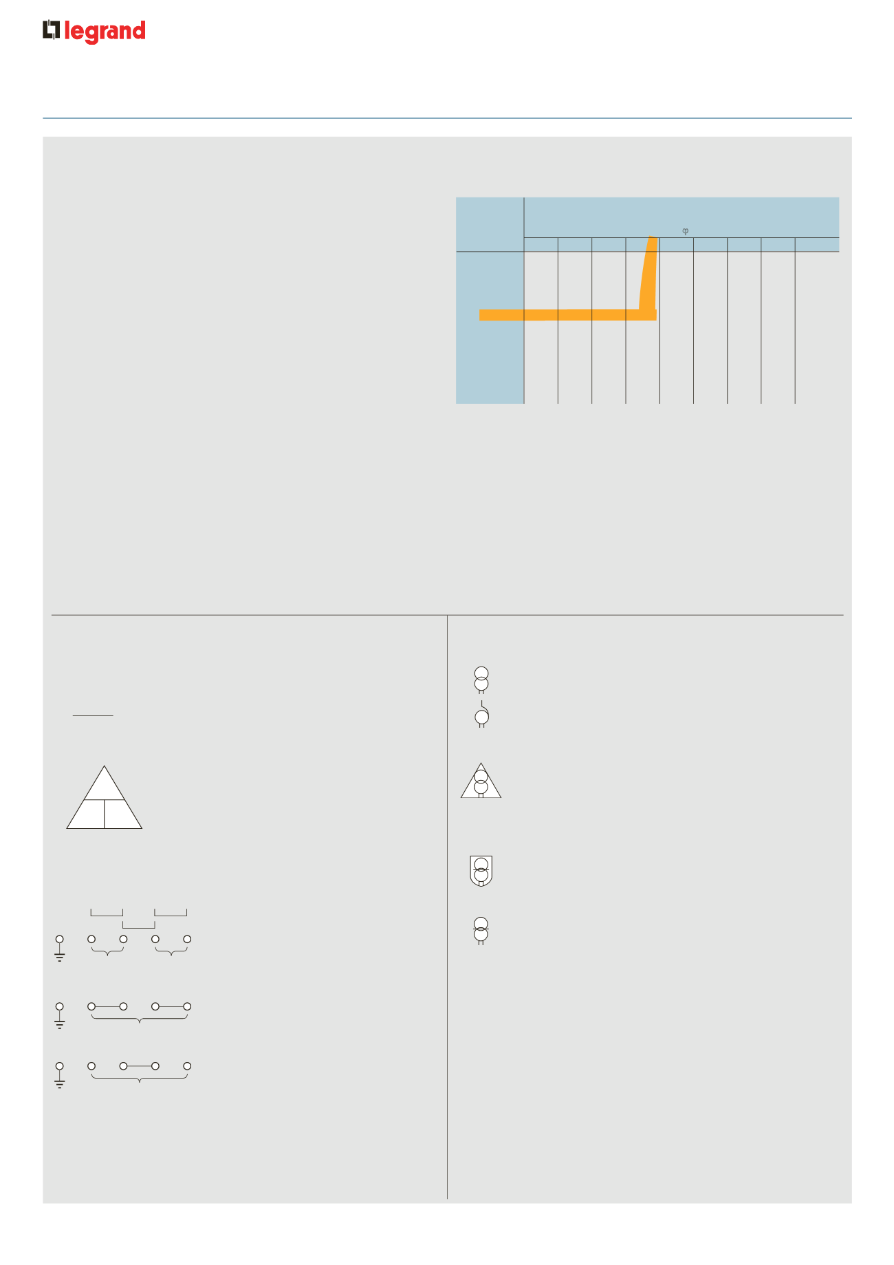
General information
The power triangle :
n
Secondary power/voltage information
Transformers take around 25 times the load at switch on
VA ÷ V = current in the winding
either PRIMARY or SECONDARY
i.e. 300 VA = 25 A x 25 = 625 A
12 V
From the example above, an inrush of 460 VA at cos
ϕ
0·5 gives a
transformer size of 250 VA
n
Checking the selection
As a precaution, make the following checks on each of your devices :
- first calculate the sum of the steady state power for the coils and the
LEDs powered at the same time
- then apply a coefficient : use either our hypothetical figure of 80%
of devices at steady state power, or the actual calculation for your
equipment
- the power of the chosen transformer shall be greater than or equal to
the result of the calculation
1 : LED = Light Emitting Diode
90
63
40
100
160
250
400
630
1 000
1 600
2 500
4 000
160
240
480
830
1 600
2 000
5 400
9 000
7 300
34 500
80
140
190
400
690
1 400
1 800
4 600
8 000
6 600
28 800
72
130
170
350
590
1 200
1 500
4 000
7 200
6 000
24 400
66
120
160
300
510
1 000
1 400
3 600
6 600
5 700
17 000
61
110
150
270
450
900
1 200
3 200
6 100
5 200
16 600
57
100
140
240
400
800
1 100
3 000
5 700
4 900
16 400
53
90
130
220
360
800
1 100
2 700
5 400
4 700
14 800
51
90
130
200
330
700
1 000
2 600
5 300
4 600
13 400
53
90
140
190
310
700
1 000
2 500
5 600
5 100
12 400
0·2 0·3 0·4 0·5 0·6 0·7 0·8 0·9
1
Admissible instantaneous power in VA IEC/EN 61558-2-2
with cos
ϕ
of :
Rated
power
in VA
IEC and CSA
n
Identification of markings
Example : compact transformer 100 VA - 12/24 V Cat. No. 0428 42
12 V
50 VA
OR
12 V
50 VA
12 V
100 VA
Link
Link
OR
24 V
100 VA
Link
P
V I
• Electric shock protection
- Protection against direct and indirect contact by :
Safety transformers (reinforced insulation
between primary and secondary, no-load voltage < 50 V)
- Protection against indirect contact by :
Circuit separation transformers (reinforced insulation
between primary and secondary)
The transformer function(s) can either be defined by the equipment
designer or can be imposed by installation guidelines or the
equipment standard
Definitions of electrical shock :
- Electric shocks : physiopathological effect resulting from an electrical
current passing through the human body
- Direct contact : persons coming into contact with live parts (connected
to the mains)
- Indirect contact : persons coming into contact with grounding which is
accidentally live following an insulation fault
Indice prote tion-1061s
Indice prot ction-1062.eps
• Changing voltage
Isolation transformer (functional insulation between
primary and secondary)
Auto transformer (no insulation between primary
and secondary)
• Control circuit power supply
Control transformer (functional insulation between
primary and secondary)
Indice alim-1060.eps
Indice tension-1058.eps
Indice tension-1059.eps
how to calculate
the rated power of a transformer