


 98 / 210

98
Accessory
10
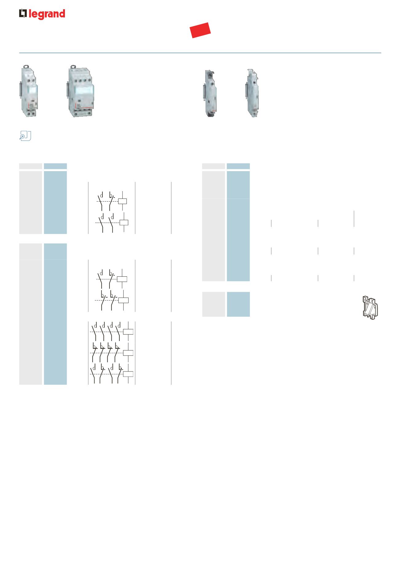
4063 07 Spacing unit 0·5 module
To be placed between every 2 contactors
to aid cooling
power contactors CX
3
without handle
16 A to 63 A
Technical information
p. 100
Dimensions
p. 103
Conform to IEC/EN 61095
Space for power supply busbar on top (up to 25 A)
Pack
Cat. Nos.
Power contactors with 24 V
±
coil
Double pole - 250 V
±
I max
Connection
Type of
contact
Number
of modules
1
4125 03 16 A
24V
N/C + N/O 1
1
4125 05 25 A
24V
2 N/O
1
Power contactors with 230 V
±
coil
Double pole - 250 V
±
I max
Connection
Type of
contact
Number
of modules
4
4125 21 16 A
230V
N/C + N/O 1
1
4125 24 25 A
230V
2 N/C
1
Four pole - 400 V
±
5
4125 35 25 A
230V
4 N/O
2
1
4125 36 25 A
230V
4 N/C
2
1
4125 33 25 A
230V
2 N/C + 2 N/O 2
Pack
Cat. Nos.
Signalling auxiliaries for CX
3
contactors
Auxiliary changeover switch
Used to signal the position status of the contacts on
the product to which it is connected
For 1 module contactors 16 A to 25 A
Maximum 2 auxiliary devices per contactor
Fitted on left-hand side of contactor
I max
Voltage
Contact
Number
of modules
1
4124 29 5 A
250 V
A
N/C + N/O 0.5
For 2 module contactors 25 A
Maximum 2 auxiliary devices per contactor
Fitted on left-hand side of contactor
1
4124 30 5 A
250 V
A
N/C + N/O 0.5
For 63 A contactors
Maximum 1 auxiliary device per contactor
Fitted on left-hand side of contactor
1
4124 31 5 A
250 V
A
N/C + N/O 0.5
4125 05
4125 35
4124 29
4124 31
NEW