


 92 / 244

0036 59
0036 58
0036 60
lighting management
remote control
dimmers
■
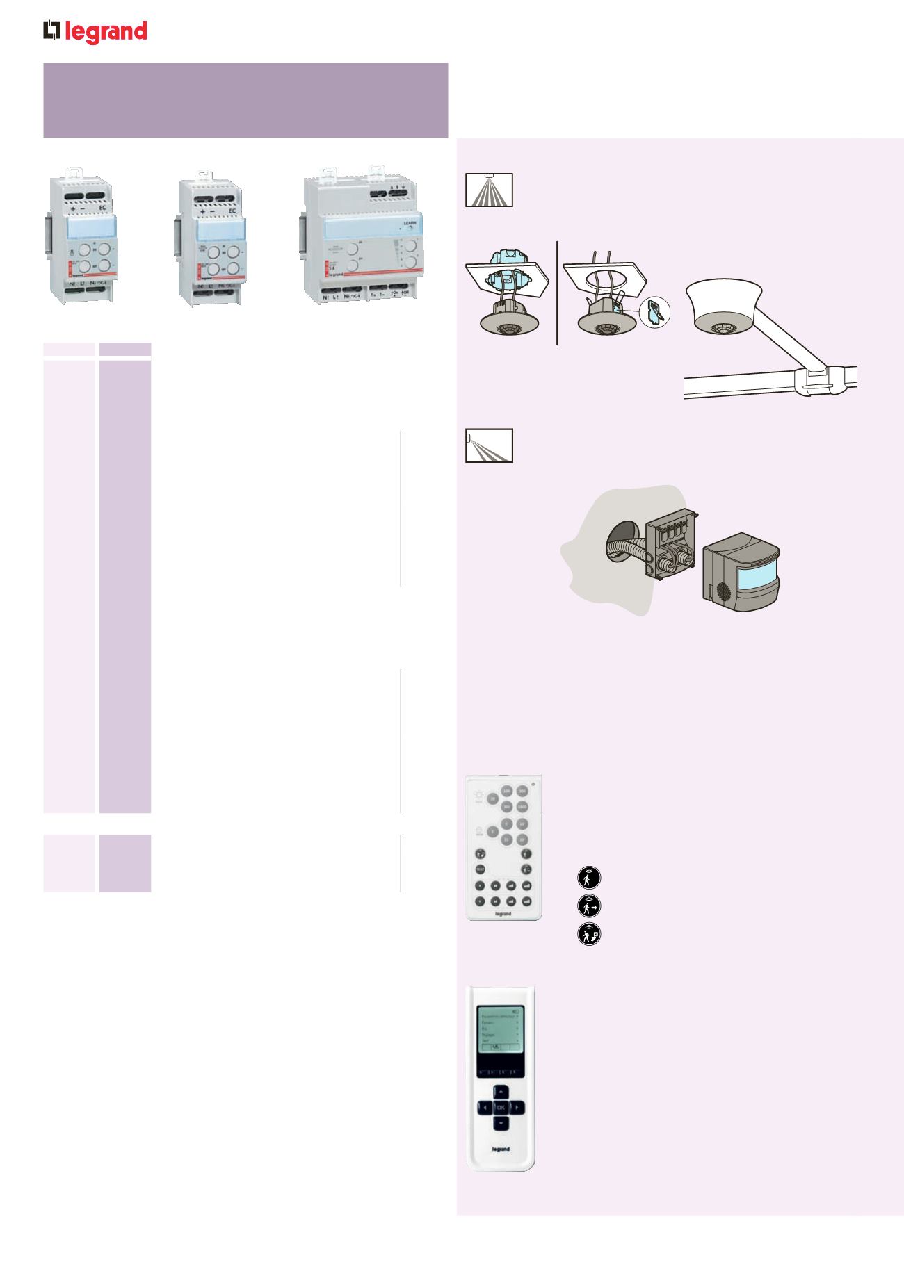
Wall mounting
Wall mounting sensors are supplied with mounting base
Simply fix base to the wall, connect wires to the automatic
wiring block and fix sensor to base
■
Ceiling mounting
All sensors have built-in bracket systems that enable ceiling
mounting. Most sensors are suitable for standard EU boxes
(Ø65). This is important for applications where the ceiling is
unavailable for sensor installation
Only one Cat. No. for two ways of mounting
For advanced configuration :
For standard configuration :
Cat. No. 0882 35
(see p. 83)
Cat. No. 0882 30
(see p. 83)
- Time level : 3, 5, 10, 15, 20 mn
- Lux level : 20, 100, 300, 500, 1000 lux
- Presence, presence walkthrough, absence modes
- PIR and US detection sensibility : low, medium,
high, very high
- test mode
Presence mode
Walkthrough mode
Absence mode
This commissioning tool enables a very precise
commissioning of your sensors :
- Time : from 0 seconds to 60 mn
- Lux : from 1 lux to 1275 lux
- Detection mode : presence, presence
walkthrough, absence modes
- PIR and US detection sensibility : low, medium,
high, very high
- Provides access to advanced functions such as
calibration, alarms, choice of mode of detection
(initial detection, maintain detection, retrigger),
daylight function
- Allows downloading, saving and duplication of
sensor parameters
Two commissioning tools can be used to adjust settings :
■
Settings
Most sensors feature Smart Factory Set technology
Adjustments are typically not needed after installation
If adjustments need to be made (due to last minute changes in furniture
or fixture placement), sensitivity and time delays should match the
activity levels of the monitored spaces
3'
lighting management
standalone sensors
installation details
Pack
Cat. Nos.
Remote control dimmers 100 - 240 V
A
-
50/60 Hz
Controlled via non-illuminated push buttons
DIN rail mounting
The last lighting level is stored into memory,
in case of power cut or switch-off
Direct or remote control (switching and
dimming) with non-illuminated push buttons
Number of
modules
1
0036 59 For incandescent and halogen lamps
230 V
A
and ELV halogen lamps with
ferromagnetic transformers
Load : 60 to 600 W (for 230 V
A
50/60 Hz)
2
1
0036 58 For fluorescent lamps with 1-10 V dimmable
ballast (fluorescent tubes and compact
fluorescent lamps with separated dimmable
ballast)
Ballast power : maximum 800 VA
(for 230 V
A
50/60 Hz)
Control current : 50 mA
2
Controlled via BUS line
DIN rail mounting
Direct or remote control (switching and
dimming) with non-illuminated double
push buttons or BUS peripherals (Arteor
Programme)
Equipped with illuminated scale indicating
the light level of controlled lamps
Number of
modules
1
0036 71 For incandescent and halogen lamps
230 V
A
, ELV halogen lamps with
ferromagnetic or electronic transformers
Load : 1000 W (for 230 V
A
50/60 Hz)
6
1
0036 60 For fluorescent lamps with 1-10 V ballast
(fluorescent tubes and compact fluorescent
lamps with separated ballast)
Ballast power : maximum 1000 VA
(for 230 V
A
50/60 Hz)
Control current : 50 mA
4
Power supply for BUS line
Number of
modules
1
0036 80 BUS power supply for remote controlled
dimmers Cat. Nos. 0036 60/71
For maximum 8 peripherals
2
84