


 209 / 430

Sales Service Centre • 01952 675612 Technical Support Helpline • 01952 675689
5.9
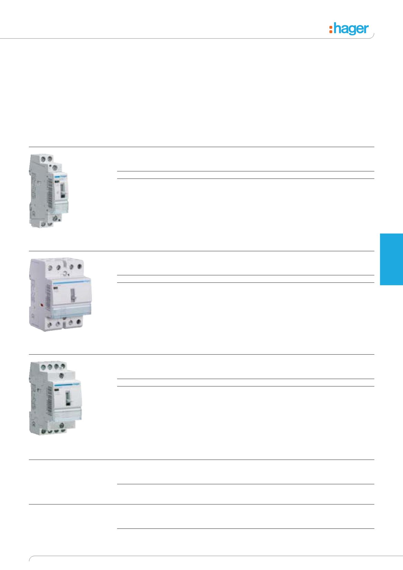
Override Contactors
Description
Manual override facility
allows temporary override, with
automatic return at next coil
energisation. Permanent off can
also be selected. ETC225S low
noise version.
Technical Data
The choice of contactor depends
upon a number of parameters,
e.g.
• The nature of the supply.
• The power it is switching.
• The characteristics of the load.
• The control voltage required.
• Number of operations
All contactors ratings are for AC1
loads only – if the load differs
from AC1 the contactor may
need de-rating (see technical
characteristics on page 5.37).
The use of LZ060 (heat
dissipation inserts) between
all contactors installed or
between contactors and
adjacent devices is
recommended.
Options
Contact choice
• Normally open (NO)
• Normally closed (NC)
Auxiliary
All contactors will accept
auxiliary, ESC080 contact.
1 Mod = 17.5mm
2 Mod = 35mm
3 Mod = 52.5mm
4 Mod = 70mm
2 NO
Coil AC voltage
Power circuit AC1
Width
Cat ref.
230V 50 Hz
25A - 250V~
1 Mod
ETC225S
1
230V 50 Hz
25A - 250V~
1 Mod
ETC225
1 Low noise device
3 NO
Coil AC voltage
Power circuit AC1
Width
Cat ref.
230V 50 Hz
20A - 400V~
2 Mod
ETC325
230V 50 Hz
40A - 400V~
3 Mod
ETC340
Auxiliary for 25A Contactors
Power circuit AC1
Width
Cat ref.
2A - 250V~
½ Mod
ESC080
Accessories
Description
Width
Cat ref.
Heat Dissipation Insert
½ Mod
LZ060
4 NO
Coil AC voltage
Power circuit AC1
Width
Cat ref.
230V 50 Hz
20A - 400V~
2 Mod
ETC425
230V 50 Hz
40A - 400V~
3 Mod
ETC440
ETC225S
ETC340
ETC425
Modular
Devices