


 96 / 108

96
Cablelink Plus Screed
Technical
screeded floor systems
customer services +44 (0)1745 532343
Top tips
l
The number and location of boxes will depend on the end user
requirements
l
If the furniture layout is available, a floor box should be considered
for each workstation or desk
l
If the final furniture layout is not available as a general guide the
minmum recommended distribution is one floor box for every
10
m
2
,
and the maximum being one floor box per 4m
2
Cablelink Plus Screed System
Cable Capacity Guide
The cable factor table below is based on the 17th Edition of the IEE Wiring
Regulations and must be regarded only as a guideline. Care should be
taken in selecting adequate trunking sections taking into consideration the
number and size of cables involved and construction of the junction box.
It is recommended that the initial design of trunking installations include
adequate provision for future wiring. To determine the size of the trunking
required, multiply the quantities of each size of conductor and appropriate
factor from Table A and compare the total with the capacity unit figure in
the appropriate Table B.
Table A - Cable Factors
Cable Type
CSA
Cable Factor
Power Cables
PVC Stranded
1.5
mm²
8.6
2.5
mm²
12.6
4
mm²
16.6
6
mm²
21.2
10
mm²
35.3
16
mm²
47.8
25
mm²
73.9
Twin & Earth
2.5
mm²
86
4
mm²
99
6
mm²
148
Data Cables
Cat 5E UTP
5.5
mm dia
30.2
Cat 5E STP
6.0
mm dia
36
Cat 6 UTP
6.5
mm dia
42.2
Cat 6 STP
7.0
mm dia
49
Sample calculation
To estimate the total number of cables that can be accommodated with a
100
x 38mm ducting:
Step 1
Pick the factor from Table B corresponding to 100 x 38 = 1563
Step 2
Select the size of the cable that needs to be pulled through the
trunking and its corresponding factor from Table A
e.g. 4mm
2
stranded = 16.6
Step 3
No. of cables = Value from (Table B / Table A)
e.g. 1563/16.6 = 94 Nos.
Table B – Metal Screed Ducting Cabling Capacity
Size
(
mm)
Compartment
size
Capacity
100%
Capacity
(45%
fill)
100
x25 100x25 (1 comp) 2205
992
100
x38 100x38 (1 comp) 3474
1563
225
x25 112x25 (2 comp)
75
x25 (3 comp)
2501
1658
1125
746
225
x38 112x25 (2 comp)
75
x38 (3 comp)
3940
2613
1773
1176
250
x25 83x38 (3 comp)
1847
831
250
x38 13x38 (3 comp)
2909
1309
275
x25 137x25 (2 comp)
91
x25 (3 comp)
3066
2035
1380
916
275
x38 91x38 (3 comp)
3206
1443
300
x25 100x25 (3 comp) 2223
1000
300
x38 100x38 (3 comp) 3503
1576
Cablelink Plus Screed System ducting complies with BS EN50085-1: 2005
and draft EN50085 Part 2-2.
The above table gives the available capacity units on 45% factor, applied to
the internal wiring area.
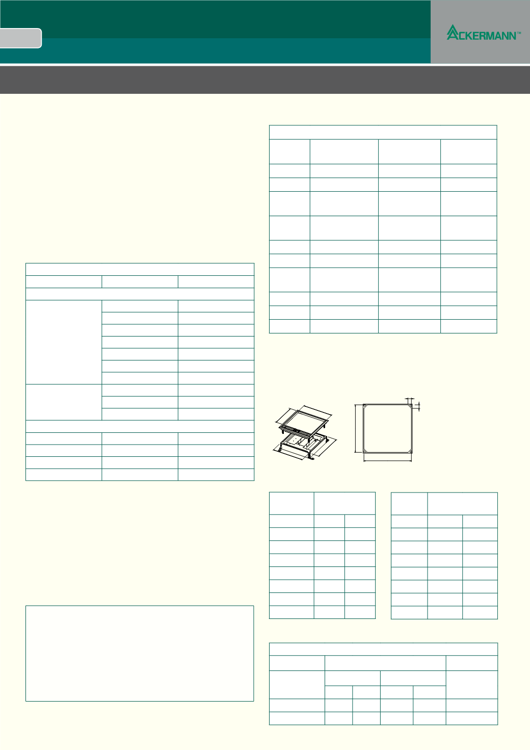
Carpet Cut out Dimensions
The table below shows the sizes required for the carpet lid infill and carpet
tile cut out for the Cablelink Plus Screed Floorboxes.
LID LIST
NUMBER
CARPET LID INFILL
DIMENSIONS (mm)
A
B
CXL100 152
93
CXL200 152 185
CXL265 219 251
CXL340 219 326
CUJL200 188 188
CUJL265 253 253
CUJL240 328 328
Where A is from left to right and B is from back to front.
BASE LIST
NUMBER
BOX CARPET CUT OUT
DIMENSIONS (mm)
C
D
CUB100 100
100
CUB200 200
200
CUB265 265
265
CUB340 340
340
CUJ200 200
200
CUJ265 265
265
CUJ240 340
340
A
B
A
B
C
D
DUCTING CABLE CAPACITY – DATA CABLES
Nominal Cable
Number of Cables
Bend Radius
Diameter mm
2
60
mm Ducting 90mm Ducting (Static on install)
@50% @75% @50% @75%
Cat 5e 5mm 30 45 63
95
20
mm + 10mm
Cat 6 6mm 20 30 44
65
25
mm + 10mm