


 98 / 108

98
Cablelink Plus Screed
Technical
screeded floor systems
customer services +44 (0)1745 532343
Cablelink Plus Screed System
Installation Guide for Underfloor Duct System
The structural floor slabs on which the underfloor ducts and boxes are to be
laid must be reasonably level and smooth. Humps and protruding cement
must be hacked to level to ensure the ducts being laid will maintain the
minimum screed thickness of 25mm over the ducts. It is recommended that
a layer of green screed be laid on the structural slab beneath the underfloor
ducts to prevent air gaps and vacuum while screeding.
1
The floor slab where junction and service outlet boxes are to be laid
should be marked out. The appropriate duct entry plates should be fastened
to the boxes.
Ducts should be laid in straight lines between points of junction boxes and
parallel to known base lines on each floor. Changes in direction of ducts
should be made with junction boxes.
Use steel fixing clips to secure the ducts on to the floor slab prior to
screeding. The intervals between two saddles should not exceed a maximum
of 2 metres.
All joints in ducts and terminations of ducts in junction boxes / vertical access
boxes should be made water tight with approved type sealing compound.
Precaution should be exercised during construction to prevent damage to
the ducts system and to ensure that the ducts and vertical boxes are free
of water, dirt, debris or any other obstruction which may impede and / or
damage the cables during pulling in.
2
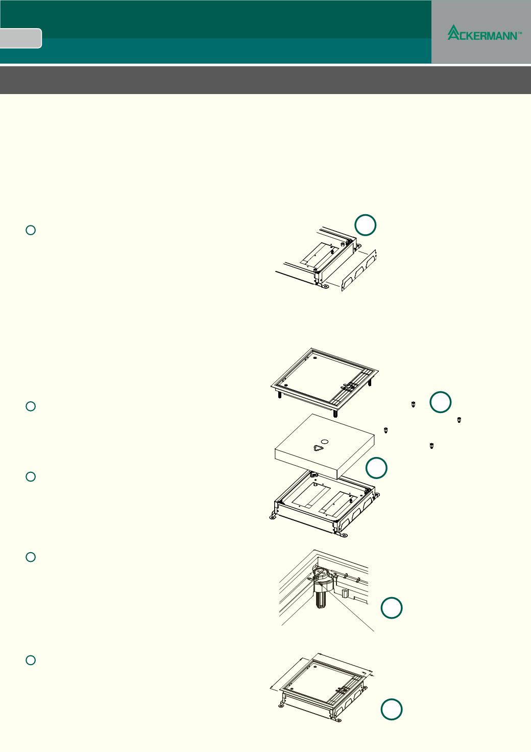
Junction and service outlet boxes should be properly covered with the
disposable lids and taped to ensure no cement gets into the boxes during
screeding.
After screeding the disposable screed cover is removed and the cable
installation can begin.
3
If extra space is required under the accessory mounting tray then height
adjuster kits can be used. The cables can now be installed and the services
terminated.
Note: The bases are supplied with 35mm wiring space, with the option to
reduce to 25mm or increase to 45mm with a height adjustment kit – part
number CUBA-1 or CUBA-2, see page 63
1
2
3
A
B
5
4
4
The frame and lid assembly can now be fitted. Ensure the ratchet
release is set to the lock position and align these with the ratchets in the
aceessory tray.
Ratchet Release
Lock Position
5
Apply gentle pressure until the frame is securely seated in the box and
against the finished floor e.g. carpet or vinyl.