


 99 / 108

99
Cablelink Plus Screed
Technical
technical hotline +44 (0)1268 563720
screeded floor systems
Cablelink Plus Screed System
6
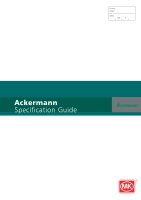
Ratchet Release
Unlock Position
6
If the frame and lid assembly requires to be removed or rotated to
ease cable egress then the ratchet releases should be rotated to the unlock
position and the frame can be lifted out of the floorbox. The assmebly can
then be rotated and fixed as before.
Note: The lid should be completely removed from the frame before
attempting to release the frame.
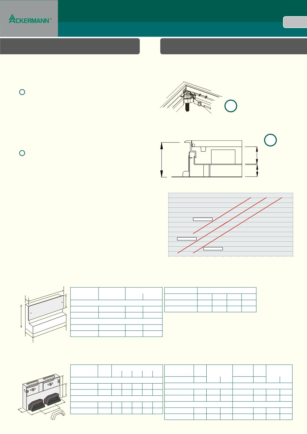
7
Plug
Clearance
Wiring
Space
Screed
Depth
7
Attention must be paid to ensure there is both sufficient wiring depth
and plug top clearance for the particular cables / plugs being used in each
installation.
50
55
60
65
70
75
80
85
90
95
100
105
110
115
10
15
20
25
30
35
40
45
50
55
60
65
70
75
80
85
90
Plug Top Clearance (mm)
25
mm Wiring Space
35
mm Wiring Space
45
mm Wiring Space
Screed Depth (mm)
Screed Depth – 25mm, 35mm and 45mm Wiring Space
This graph enables the specifier / installer to determine which depth the
screed (plus floor covering) must be in order to achieve a certain accessory
wiring space and plug top clearance within the floorbox. For example if the
specifier requires a 35mm standard wiring depth and a 45mm plug top
clearance then the graph shows that an 82mm screed (plus floor covering)
depth is required. Alternatively, if the depth is fixed, at 90mm for example,
then by having a 45mm wiring space the resulting plug top clearance will
be 43mm. If additional plug top clearance is required then the wiring depth
can be reduced to 35mm or even 25mm providing a plug top clearance of
53
mm or 63mm respectively. Care must be taken to ensure there is sufficient
wiring depth and plug top clearance for each individual installation.
Vertical Access Boxes: Metal Ducting
A
F
B
C
E
D
List Number To Suit Box Cover Plate Dims
A (mm) B (mm)
Flush Cover Plate (supplied a standard)
n/a
CUV265
265 90
n/a
CUV340
340 90
Overlapping Cover Plate
CUVP265 CUV265
285 100
CUVP340 CUV340
360 100
List Number
Box Dimensions (mm)
C D E
F
CUV265
265 85 50 200
CUV340
340 85 50 200
A
E
C
B
D
List Number Type Dimensions in mm
A
B C
D E
Shallow
SF88152
Twin 260 170 50 110 100
SF88153
Triple 370 170 50 110 100
Full Access
SF88172
Twin 260 270 50 110 100
SF88173
Triple 370 270 50 110 100
List Number Type Dimensions
in mm
List
Number
Type Dimensions
in mm
A B
A B
Overlapping Shallow
Flush Shallow
SF88180
Twin 280 80 SF88176 Twin 260 70
SF88181
Triple 390 80 SF88177 Triple 370 70
Overlapping Full Access
Flush Full Access
SF88188
Twin 280 180 SF88184 Twin 260 170
SF88189
Triple 390 180 SF88185 Triple 370 170
Vertical Access Boxes: PVC Ducting
Cover Plates