


 665 / 759

18mm
87mm
120mm
15mm
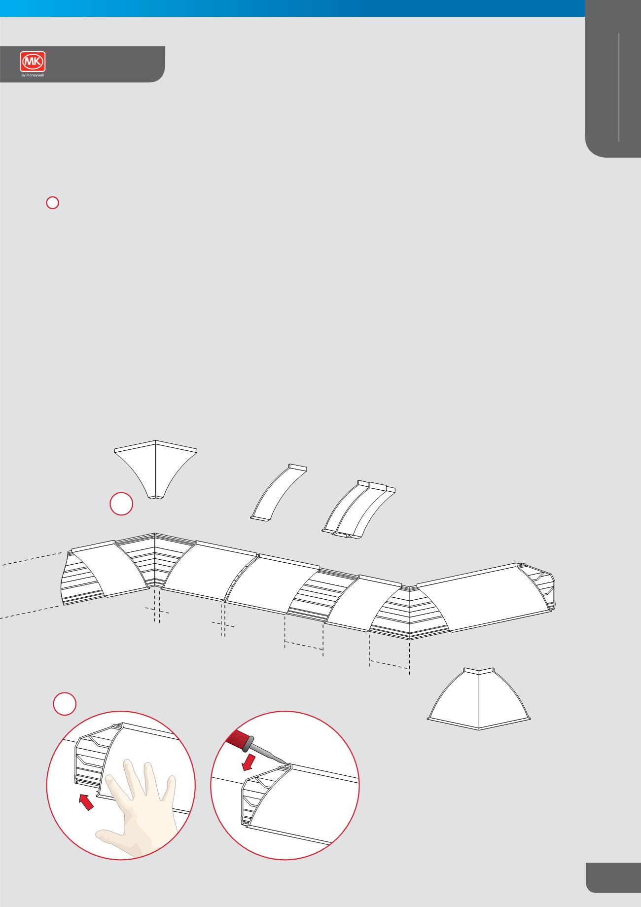
External Corner
Internal Corner
Joint Cover
Mini Trunking
Adaptor
3
Covers
Installation
– Locate the top edge, adjacent to the ceiling,
with upper back clip.
The lower clip is then fitted by exerting pressure against
the front face, pushing towards the wall (Standard Cornice
Shown).
Removal
– Gain access to the interior of the trunking.
Remove one of the accessory mouldings and carefully insert
screwdriver, under the top edge and lever forward so as to
disengage clip.
In restricted spaces, engage a hook behind the ceiling edge
of the cover, and pull forward to disengage.
The lower clip is then disengaged in the same way.
Notes
Jointing
– Where gaps occur, a gap of 5mm must be left
between base sections to allow for expansion. The cover must
overlap this joint by a minimum of 50mm.
Finishing
– In circumstances where the wall or ceiling is uneven,
a flexible sealer or mastic can be used to fill any gaps which occur
along the edge of the trunking. Relief finishes, such as Artex,
must be smoothed down with a spatula, for a width of 25mm
minimum, along the line of the trunking in order to enable cover
removal.
4
4
Technical Hotline
+44 (0)1268 563720
665
CABLE MANAGEMENT
PERIMETER AND
DISTRIBUTION
Ega Cornice
Technical