


 664 / 759

1
2
Ceiling
Top edge
Lower clip
Rib on
wall surface
Wall
Ceiling
Top edge
Lower clip
Rib on
wall surface
Wall
Ceiling
Top edge
Lower clip
Wall
Standard Cornice
Compact Cornice
Cornice Trunking
Installation Guide
General notes
Prior to installation strike a line of trunking using a plumb and
chalk line for vertical, and spirit levels for horizontal runs.
1
Installation
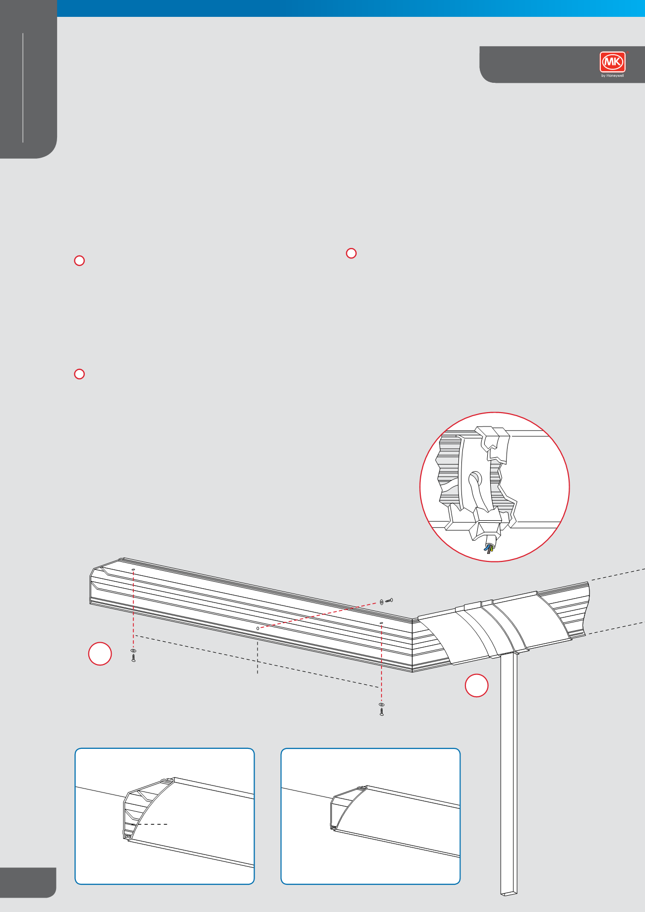
a
Separate the cover from the backing. Measure the walls and
cut trunking base to length making due allowance for external
corner mitres. Fix base to wall/ceiling using woodscrews or
bolts, with large washers. Oversized holes must be drilled to
allow for expansion.
b
The base should be fixed to both wall and ceiling at 500mm
intervals giving a staggered arrangement
2
Spurs
a
Spurs from the main Cornice trunking across ceilings or
down walls are made using a Mini Trunking Adaptor (CA1
for Compact or CA2 for Standard) in conjunction with the
appropriately sized Mini Trunking spout adaptor.
b
In Standard Cornice, the cable retaining strap enables cables
to be segregated from other services used in conjunction with
a mini trunking adaptor. A hole of 25mm or less must be drilled
and the cable should be looped through the aperture as shown.
A cable retraining strap is also available for Compact C rnice.
Locate ceiling and wall spur then mark base to indicate the
end of the lid run. Fit Ega Mini Trunking as appropriate using
the relevant Mini Trunking spout adaptor (YEA). Install wiring
using retaining strap(s) as necessary.
3
Corners and Accessories
a
Mitre base to ensure moulded accessories fit. Cut lid
square having made suitable allowance for the width of the
accessories and the overlap required to fit under joint covers.
b
All fittings clip onto an exposed section of the trunking base.
Allow suitable gaps in trunking lid.
Mark the base with position and width of the accessories and
cut the lid the appropriate length, taking due notice of the gap
allowances. (Standard Cornice shown).
500mm
500mm
mkelectric.co.uk664
CABLE MANAGEMENT
PERIMETER AND
DISTRIBUTION
Ega Cornice
Technical