


 550 / 759

WIRING DEVICES
mkelectric.co.ukINGRESS PROTECTED
IP66
550
Installation
Notes
1.
The enclosure is made from polycarbonate which is a highly
durable material, and ideal for most environments. However, if
installing in areas where creosote, some chemicals, synthetic
oils and harsh cleaners are used, seek advice from MK
Technical Sales Service Department or refer to the table on
page 552.
2.
The enclosure must be mounted on a flat, vertical surface that
is free from grease, dirt and loose material.
3.
If the conduit cable entry is from the top or sides the lower
drain hole in the mounting box must be drilled out using a 5mm
diameter drill bit. This will allow any condensation formed in the
conduit system to drain out of the unit.
NOTE: opening the drain hole will reduce the IP rating; therefore ensure
that jetted water is not directed at the unit.
4.
The drain hole should not be drilled out if the enclosure is to be
installed in an excessively dusty environment. If the drain hole
is not drilled out, only the bottom cable entry must be used.
5.
If conduit is used for bottom cable entry, a 5 mm diameter drain
hole needs to be drilled in the lowest point of the conduit run.
6.
If wiring directly to the enclosure without conduit and the
installation is outdoors, ensure that a cable specified for
outside use is used.
7.
PVC Cable Entry (see Service Items) must only be used at the
bottom cable entry of the enclosure.
NOTE: If using box coupler 56464 to join boxes use a suitable sealant
to ensure full IP protection is maintained.
Instructions
CAUTION
Do not allow paint or wood preservative to come into contact
with the product. The product can be safely mounted on painted
surfaces or surfaces treated with wood preservative when the
paint or wood preservative is completely dry.
1.
Read the safety instructions.
2.
Mark the position of the fixing holes for the mounting box.
3.
Drill holes and fit wall plugs suitable for a No. 8 wood screw.
4.
Prior to fitting the mounting box to the wall, drill out the drain hole
if required (see Installation Note 3). File out the complete drain
hole profile. Take care not to damage the small internal wall.
5.
Carefully remove the cable entry blanks, or drill out the rear
cable entry, as required and fit conduit entry (see Service Items).
6.
Secure the mounting box to wall with four No. 8 wood screws.
Position drain hole at bottom left hand corner.
7.
Align and install conduit or cable entry as required.
8.
Seal the conduit and conduit entry with a non setting conduit
sealant such as EWPLUS. Refer to Figure 4.
9.
For instructions on how to wire the front plate of telephone
and data products see the instruction leaflets supplied with the
appropriate module.
10.
Before wiring and fitting the front plate, position the seal on the
front plate. Ensure the holes are aligned and seal is aligned
with the ribs on the mounting box and the cables are threaded
through the seal and screws are fully tightened.
eal Plus
™
6 Weatherproof
es
A. PRODUCT FEATURES
The Masters al Plus range consists of various surface mounted and flush
mounted products and associated bezels and service items.
The Masterseal Plus range of products are robust and made from a tough
thermoplastic material suitable for interior and exterior use wherever
cor osion re istance, dirt a d moisture proofing is required.
All products accept MK push in conduit and cable entries that complement
the range. See Service Items.
Masterseal Plus socket outlets will accommodate most 13A prewired and
rewirable domestic plugs.
The Masterseal Plus range of produc s offer an ingress protect on code of
IP66 when the product is in or not in use. Providing the product is correctly
installed, the lid is closed (see fig.1) and the cable correctly positioned
through the centre of the gel seal.
Note: This product is not suitable for appliances that have a transformer
built into the plug or for plugs that have non standard extensions or
protrusions.
If you are in any doubt regarding this range of products, please contact
MK Technical Sales Service Department on:
+44 (0) 1268 563720 or
mk.technical@honeywell.comAll products conform to their releva t National standard as well s the
standard for enclosures BSEN60439-1, European 10/16A sockets conform
to IEC 60884-1, 13A Sockets conform to BS1363: Part 2 and Connection
Units to BS1363: Part 4.
2
B. SERVICE ITEMS
3
C. SAFETY IN
SWITCH OFF AND
OUT INSTALLATIO
1. The Masterseal P
extra low voltag
outlets must not
(110 V – 250 V 5
2. This product mu
with the current
Building Regulat
If in any doubt co
3. It is essential tha
not stressed and
4. When installing
provided from t
socket outlet. T
inside the enclos
5. If metal conduit
must be maintai
6. At the end of th
disposed of via
BURN.
which is a highly durable material,
if installing in areas where creosote,
aners are used, seek advice from
ertical surface that is free from
sides the lower drain hole in the
mm diameter drill bit. This will
it system to drain out of the unit.
IP rating; therefore ensure that
he enclosure is to be installed in an
hole is not drilled out, only the
5 mm diameter drain hole needs to
t run.onduit and the installation is
outside use is used.
cabling in the UK since April 2004
ws;
'.
ere;
'.
nly be used at the bottom cable
INSTRUCTIONS:
CAUTION
Do not allow paint or wood preservative to come into contact with the
product. The product can be safely mounted on painted surfaces or
surfaces treated with wood preservative when the paint or wood
preservative is
completely dry.
1. Read the safety
instructions.
2. Mark the position
of the fixi g holes
for the mounting
box.
3. Drill holes and fit
wall plugs suitable
for a No. 8 wood
screw.
4. Prior to fitting the
mounting box to
the wall, drill out
the drain hole if
required (see Installation Note 3). File out the complete drain hole
profile. Take care not to damage the small internal wall.
5. Carefully remove the cable entry blanks, or drill out the rear cable entry,
as required and fit conduit entry (see Service Items).
6. Secure the mounting box to wall with four No. 8 wood screws. Position
drain hole at bottom left hand corner.
6
7. Align and install conduit or cable entry as required.
8. Seal the conduit and conduit entry with a non setting conduit sealant
such as Egaweld™ Plus Refer to Figure 4.
7
9. For instruction
products see t
module.
re reference
List No.
Description
Dimensions
56837 Cable Seal Capsule
34.7 x 11.6 x 11.5
56460 Entry Blank
26.9 dia x 5.25
56461 PVC Cable Entry
26.9 dia x 10.15
56462 20 m Plain Conduit Entry
26.9 dia x 28
56463 20 mm Threaded conduit Entry
26.9 dia x 28
56464 Box Coupler
26.9 dia x 16.5
9933 M20 Earth Lead Adaptor
1G 95mm
(2G 96 mm)
Centre
Line of
Conduit or
Cable
Entry
1G 95 mm (2G 157mm)
One Gang
(Two Gang)
Figure 2
Figure 3
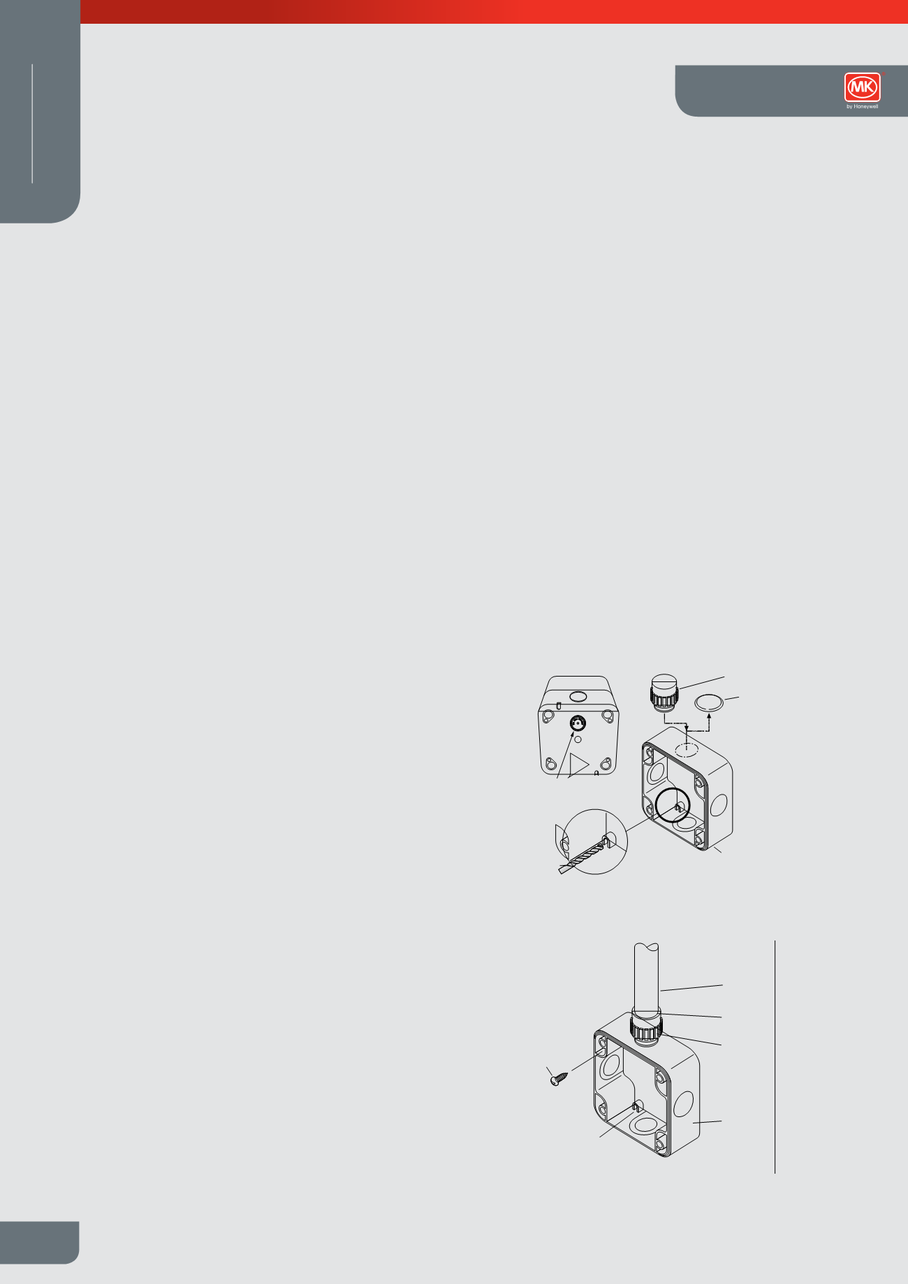
TOP
Conduit Entry
Entry Blank
Drain Hole
Drill Out Feature
5 mm
Drill Bit
Mounting
Box
No 8 Wood Screw
Figure 1
2 Page 1
urface mounted and flush
ervice items.
st and made from a tough
exterior use wherever
is required.
ble entries that complement
te most 13A prewired and
ingress protection code f
ding the product is correctly
ble corr ctly positioned
s that have a transformer
andard extensions or
products, please contact
ll.comstandard as well as the
n 10/16A sockets conform
3: Part 2 and Connection
B. SERVICE ITEMS
3
C. SAFETY INSTRUCTIONS
WARNING
SWITCH OFF AND ISOLATE THE MAINS SUPPLY BEFORE CARRYING
OUT INSTALLATION OF THE MASTERSEAL PLUS PRODUCT.
1. The Masterseal Plus Euro Data Enclosure (K56423) is intended for use with
extra low voltage data and telephone modules. Data and telephone
outlets must not be mixed with other modules intended for mains supply
(110 V – 250 V 50/60 Hz).
2. This product must be installed by a competent person in accordance
with the current editions of the IEE Wiring Regulations (BS7671) and
Building Regulations.
If in any doubt consult a qualified electrician.
3. It is essential that all connections are made as instructed that cables are
not stressed and terminals are fully tightened.
4. When installing socket products an earth continuity conductor must be
provided from the origin of the installation to the earth terminal of the
socket outlet. This earth conductor must be sleeved (Green/Yellow)
inside the enclosure.
5. If metal conduit is used in more than one cable entry earth continuity
must be maintained between conduits.
6. At the end of their useful life the packaging and product should be
disposed of via a suitable recycling centre where facilities exist. DO NOT
BURN.
4
ome into contact with the
on painted surfaces or
n the paint or wood
he complete drain hole
internal wall.
drill out the rear cable entry,
e Items).
o. 8 wood screws. Position
7. Align and install conduit or cable entry as required.
8. Seal the conduit and conduit entry with a non setting conduit sealant
such as Egaweld™ Plus. Refer to Figure 4.
7
9. For instructions on how to wire the front plate of telephone and data
products see the instruction leaflets supplied with the appropriate
module.
8
List No.
Description
Dimensions
56837 Cable Seal Capsule
34.7 x 11.6 x 11.5
56460 Entry Blank
26.9 dia x 5.25
56461 PVC Cable Entry
26.9 dia x 10.15
56462 20 mm Plain Conduit Entry
26.9 dia x 28
56463 20 mm Threaded conduit Entry
26.9 dia x 28
56464 Box Coupler
26.9 dia x 16.5
9933 M20 Earth Lead Adaptor
1G 95mm
(2G 96 mm)
(2G 157mm)
ne Gang
wo Gang)
Figure 2
Figure 3
TOP
Conduit Entry
Entry Blank
Drain Hole
Drill Out Feature
5 mm
Drill Bit
Mounting
Box
Mounting Box
Drain Hole
Conduit
Sealant
Conduit
Entry
No 8 Wood Screw
Figure 4
Figure 1
Masterseal Plus™
Technical