


 551 / 759

WIRING DEVICES
Technical Hotline
+44 (0)1268 563720
INGRESS PROTECTED
IP66
551
Installation
11.
Wire and fit the front plate. Ensure the seal is correctly located
and the cables are not trapped or pinched.
When installing connection units using the
front flexible cable clamp
1.
Strip back the outer sheath on the appliance flexible LOAD
cable and trim wires to 55mm in length. Do not trim the
insulation on the three individual cables for the moment.
2.
When using cables of 10mm or more in diameter, it is
necessary to prestress the cable clamp before attempting to
load the cable.
3.
To pre-stress the clamp insert a flat bladed screwdriver into the
cord grip as shown in fig. 6a and flex the clamping jaw open
until it touches the grey base moulding fig. 6b. Then remove
the screwdriver.
IMPORTANT: The clamp must not be re-used for cables below 6mm
diameter after pre-stressing.
4.
Cables below 10mm diameter do not need the cable clamp
pre-stressed and the installation from this point is the same for
all products.
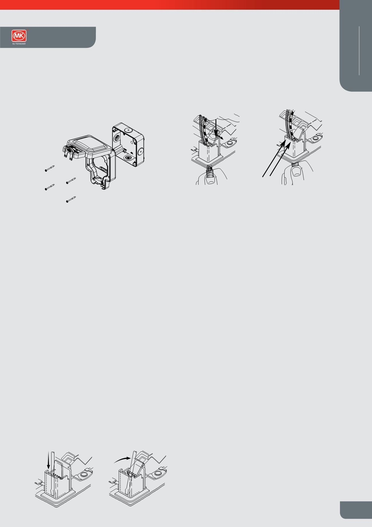
5.
To assist pushing the load cable through the front of the
product, ease the clamping jaw pressure by holding the
product securely in one hand and pushing the tab firmly with
your thumb in the direction shown in fig. 7a.
6.
Continue pushing the cable through the clamp until the outer
sheath reaches the cable stops. See fig. 7b. The jaws must
clamp on the outer sheath.
7.
Carefully strip back the insulation on all three cables to expose
10mm of the conductor.
8.
Ensure all conductors are connected to the appropriate terminals.
NOTE: Terminal screws must be securely tightened. Pull on each cable to
ensure that the terminal screw has securely fixed the conductor.
WHEN INSTALLING CONNECTION UNITS USING THE FRONT FLEXIBLE
CABLE CLAMP
1. Strip back the outer sheath on the appliance flexible LOAD cable and
trim wires to 55mm in length. Do not trim the insulation on the three
individual cables for the moment.
2. When using cables of 10mm or more in diameter, it is necessary to pre-
stress the cable clamp before attempting to load the cable.
3. To pre-stress the clamp insert a flat bladed screwdriver into the cord
grip as shown in
fig. 6a
and flex the clamping jaw open until it touches
the grey base moulding
fig. 6b
. Then remove the screwdriver.
IMPORTANT: The clamp must not be re-used for cables below 6mm
diameter after pre-stressing.
4. Cables below 10mm diameter do not need the cable clamp pre-stressed
and the installation from this point is the same for all products.
5. To assist pushing the load cable through the front of the product, ease
the clamping jaw pressure by holding the product securely in one hand
and pushing the tab firmly with your thumb in the direction shown in
fig. 7a
.
6. Continue pushing the cable through the clamp until the outer sheath
reaches the cable stops. See
fig. 7b
. The jaws must clamp on the outer
sheath.
7. Carefully strip back the insulation on all three cables to expose 10mm of
the conductor.
8. Ensure all conductors are connected to the appropriate terminals.
Terminal screws must be securely tightened. Pull on each cable to
ensure that the terminal screw has securely fixed the conductor.
9
10
11
13
14
15
G. SPECIFICATION
All MK products are manufactured in accordance with
ISO9001: 2008 and where applicable, comply with the EMC and/or LV
directives 89/336/EEC and 73/23/EEC.
Operating Temperature range –5ºC to +40ºC
H. GUARANTEE
The company undertakes to replace or re
become defective within 20 years in the c
Device products and 10 years in the case
Wiring Device products and all Circuit Pr
products solely as a result of faulty materi
Understandably if the product has not be
accordance with the company’s instructio
appropriately or if any attempt has been
the product in any way the guarantee will
This guarantee states the company’s entir
cover consequential loss or damage or in
defective product. This guarantee does n
statutory or other rights of the customer.
Repair of goods after the guarantee pe
If the product fails under normal use afte
contact your local dealer or stockist.
MK Electric Limited wishes to make it cle
designs of the products that it manufactu
leaflet) and that it will take all necessary a
against any party found to be manufactur
otherwise dealing with any article which i
intellectual property in its own products,
therein.
Tab Pushed
This Way
Installatio
flexible l
cables
Figure 7a
Figure 6a
Pre-stressing the
clamp for cables
10mm in di
10. Before wiring and fitting the front plate, position the seal on the front
plate. Ensure the holes are aligned and seal is aligned with the ribs on
the mounting box and the cables are threaded through the seal and
screws are fully tightened.
11. Wire and fit the front plate. Ensure the seal is correctly located and the
cables are not trapped or pinched.
Figure 5
Figure 8
50048741:RevA 21/4/10 09:33 Page 2
Testing
Test the completed installation in accordance with the latest
edition of the IET wiring regulations (BS 7671).
Service and Maintenance
CLEANING
1.
The exterior of the product must only be cleaned with a
solution of mild detergent (e.g. washing up liquid) and
warm water.
E. TESTING
Test the completed installation in accordance with the latest e
IEE wiring regulations (BS 7671).
F. SERVICE AND MAINTENANCE
CLEANING
1. The exterior of the product must only be cleaned with a soluti
detergent (e.g. washing up liquid) and warm water.
CABLE SEAL CAPSULE REPLACEMENT
1. Note the orientation of the cable seal capsules in the lid an
Figure 6a
Figure 6b
Pre-stressing the front cable
clamp for cables greater than
10mm in diameter
CONNECTION UNITS USING THE FRONT FLEXIBLE
ter sheath on the appliance flexible LOAD cable and
m in length. Do not trim the insulation on the three
for the moment.
s of 10mm or more in diameter, it is necessary to pre-
lamp before attempting to load the cable.
clamp insert a flat bladed screwdriver into the cord
ig. 6a
and flex the clamping jaw open until it touches
ulding
fig. 6b
. Then remove the screwdriver.
lamp must not be re-used for cables below 6mm
stressing.
m diameter do not need the cabl clamp pre-stressed
n from this point is the same for all products.
the load cable through th f ont f the product, ease
pressure by holding the product securely in one hand
b firmly with your thumb in the direction shown in
fig. 7a
.
the cable through the clamp until the outer sheath
stops. See
fig. 7b
. The jaws must clamp on the outer
k the insulation on all three cables to expose 10mm of
tors are connected to the appropriate terminals.
ust be securely tightened. Pull on each cable to
rminal screw has securely fixed the conductor.
10
11
14
15
ION
manufactured in accordance with
where applicable, comply with the EMC and/ r LV
C and 73/23/EEC.
ure range –5ºC to +40ºC
H. GUARANTEE
The company undertakes to replace or repair at its discretion products that
become defective within 20 years in the case of electromechanical Wiring
Device products and 10 years in the case of mains related electronic
Wiring Device products and all Circuit Protection and Cable Manag ment
products solely as a result of faulty materials and or workmanship.
Understandably if the product has not been installed or maintained in
accordance with the company’s instructions, has not been used
appropriately or if any attempt has been made to rectify, dismantle or alter
the product in any way the guarantee will be invalidated.
This guarantee states the company’s entire liability. It does not extend to
cover consequential loss or damage or installation costs arising from the
defective product. This guarantee does not restrict or infringe the normal
statutory or other rights of the customer.
Repair of goods after the guarantee period
If the product fails under normal use after expiry of the guarantee period,
contact your local dealer or stockist.
MK Electric Limited wishes to make it clear that it owns all the original
designs of the products that it manufactures (whether or not listed in this
leaflet) and that it will take all necessary action in any part of the world
against any party found to be manufacturing, distributing, selling or
otherwise dealing with any article which infringes the Company’s
intellectual property in its own products, or any other right of the company
therein.
Figure 7b
Tab Pushed
This Way
Installation of
flexible load
cables
Figur 7a
Cable
Stops
Figure 6a
Figure 6b
Pre-stressing the front cable
clamp for cables greater than
10mm in diameter
Masterseal Plus™
Technical