


 451 / 759

451
WIRING DEVICES
Technical Hotline
+44 (0)1268 563720
Filtered Switchsocket Outlets
Product features
Ensure that the connecting pins protruding from the bottom of
the replacement Filter Cassette are not damaged or bent before
installation. If in doubt, contact MK Technical Sales Service
Department on +44 (0)1268 563720.
The MK Filtered Switchsocket, in common with many other
filters uses Voltage Dependant Resistors for spike suppression
purposes. The performance of these devices will eventually
degrade with use to a level where they will no longer provide
adequate protection.
When this occurs the spike filer performance of the MK Filtered
Switchsocket outlet can be restored by replacing the filter cassette.
When the filter cassette needs replacing, the green indicator on
the Replacement Filer Cassette will glow red or go out, an audible
beep every five seconds may also be heard.
Note: As with all filters, these Filter Sockets will reduce the magnitude
of RFI and spikes and consequently their ability to interfere with
connected equipment. They will not completely remove the
interference from the supply.
4.
Fit the new filter cassette by carefully sliding it into the aperture
and gently pushing it down while turning the screw clockwise
until the filter cassette is flush with the surface. Do not turn
the screw any further as this will cause distortion of the plastic
mouldings.
Product and packaging can safely be disposed of via standard
refuse facilities at the end of its useful life.
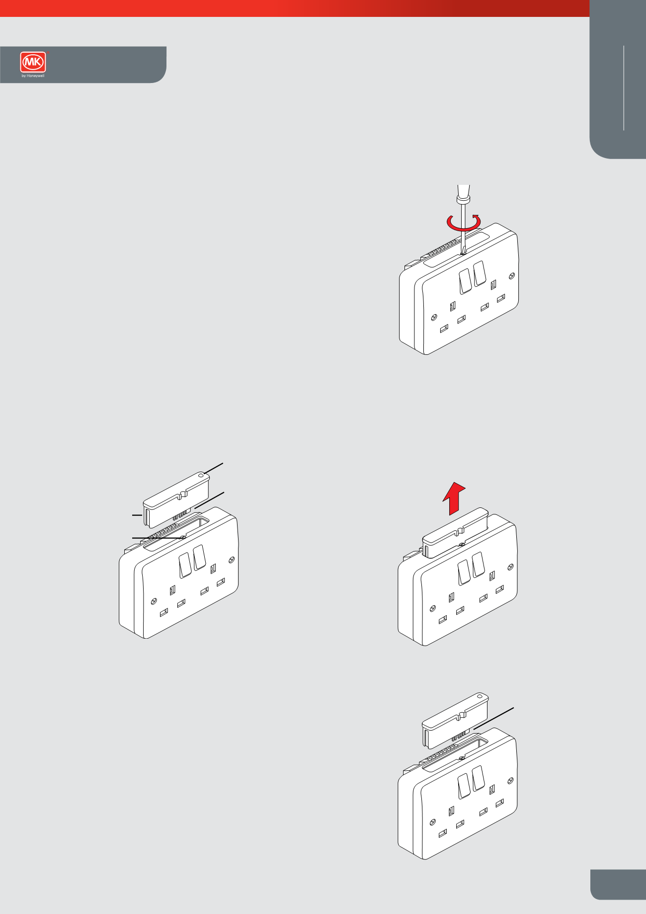
Replacement
filter cassette
Locking screw
Audible warning
connector
Filter indicator
Replacem nt
filter cassette
Locking screw
Audible warning
connector
Filter indicator
Audible warning
connector
Filter indicator
Figure 1
Figure 2a
Audible warning
connector
Figure 2
Figure 2b
Installation
Replaceable Spike Filter Cassette
Note:
To ensure a safe installation;
l
this product should be installed by a competent person.
l
it is important that all connections are made as instructed.
1.
The filter cassette can be removed and replaced without switching
off the mains or removing any plugs from the filter socket.
2.
Remove the filter cassette by turning the jacking screw anti-
clockwise to partially eject it (see Figure 2), and then gently
pulling the cassette upwards, (see Figure 2a).
3.
Only fit the MK Replacement Filter Cassette (K1800WHI).
Unpack the new filer cassette and check that the pins along the
bottom edge are not bent or broken. If these pins are damaged,
do not fit the replacement cassette. The audible sound indicating
that the filter cassette needs replacing, is optional. It may be
prevented by removing the small connector on the two end pins,
(see Figure 2b), before fitting it into the socket.
Wiring Devices Technical