


 4 / 38

Busbar Systems
General data
10/4
Siemens LV 10 · 2014
10
■
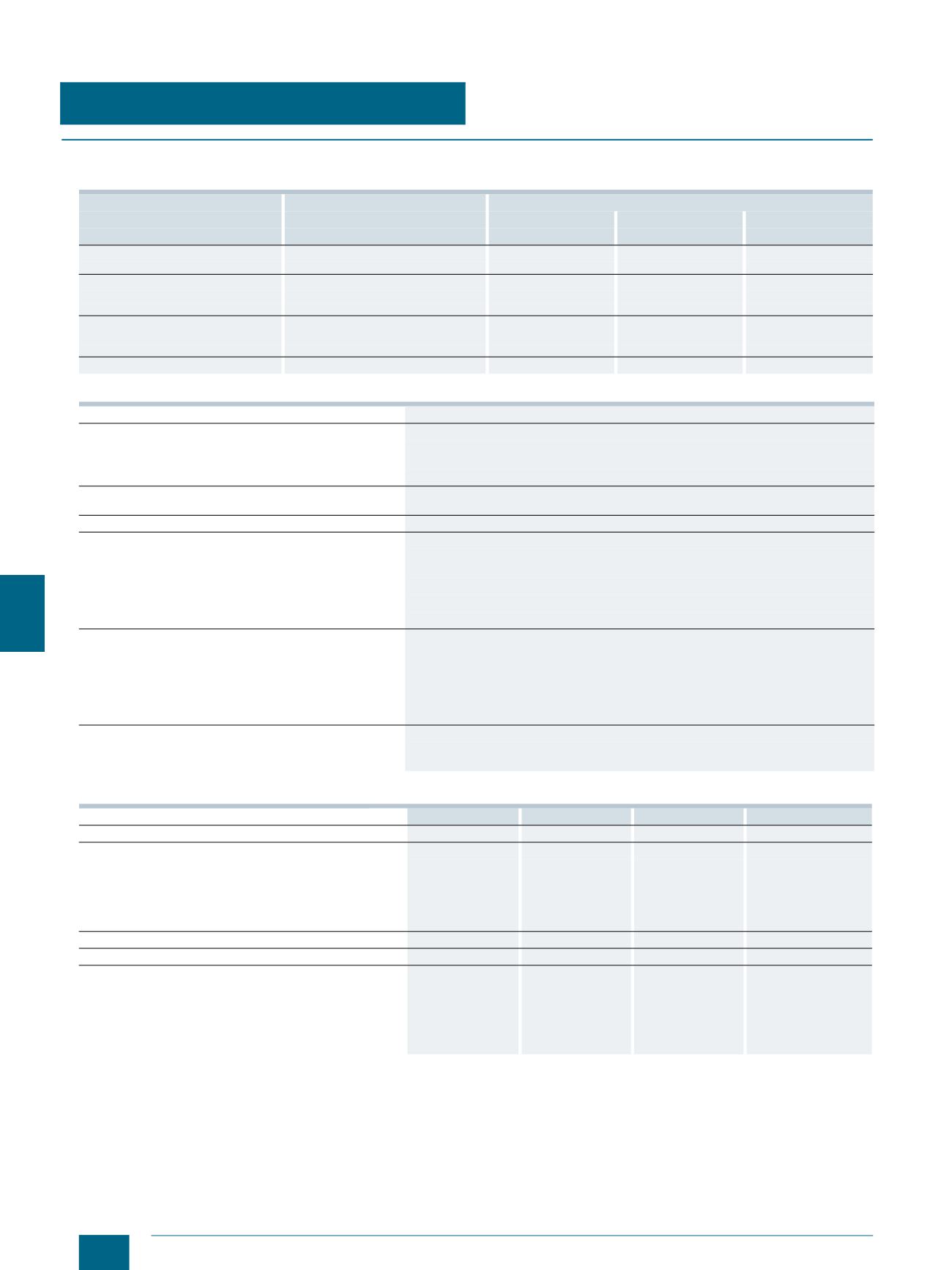
Technical specifications
Continuous current for busbars, E-Cu bare, at 35 °C ambient temperature according to DIN 43671
General technical specifications
Technical specifications of the system components
Bar dimensions
System
Continuous current at a busbar temperature of
65 °C
85 °C
105 °C
mm
mm
A
A
A
12
5
40 + 60
188
248
295
15
5
40 + 60
222
293
349
20
5
60
274
362
430
25
5
60
327
432
513
30
5
60
379
500
595
12
10
40 + 60
302
398
474
20
10
60
427
564
670
30
10
60
573
756
900
Special profile up to 1 600 A
60
1 020
1 020
1 600
Rated insulation voltage
U
i
V AC
1 000
Short-circuit strength
of 8US1 busbar device adapter
Current limitation due to associated motor starter protectors/circuit breakers/load feeders up
to 50 kA
of the busbar systems
see Characteristic Curves
Material of the 8US1 busbar supports, busbar device
adapters and device holders
Glass-fiber reinforced polyamide
Color
RAL 7035, light gray
Thermal stability (minimum values)
Busbar supports, busbar device adapters,
device holders, infeed and caps
°C 120
AWG connecting cables
°C 105 / 150
Cover profiles
°C 110
Bases, partitions, edge profiles and blanking covers
°C 70
Machining of plastic profiles
Take care when machining that no cracks are formed. A cross-cut circular saw with the
following characteristic values has proven successful in cutting cover profiles for busbars:
• D = 300 mm, B = 2.2 mm,
• T = 120 R (5° negative replaceable tooth at a cutting rate of 50 ... 60 m/s)
• Tooth feed 0.05 ... 0.1 mm
The plastic parts are secured so that vibration is ruled out.
Approvals
Busbar supports, busbar device adapters,
device holders and terminals
UR, CSA, c
u
US-
Listed
Infeed, connection modules, three-phase
5SH3538
5SH3535
8US1921-1BA00 8US1921-1AA00
Busbar center-to-center spacing
mm 60
60
60
60
Current carrying capacity of the terminal points
A 80
560
300
440
The specified current carrying capacities reflect the ther-
mal load capability of the terminal points under favorable
conditions (with the largest conductors it is possible to
connect). This does not invalidate the assignment of con-
ductor cross-sections and current carrying capacities as
defined in national and international specifications.
Tightening torque
Nm --
30
8 ... 10
12 ... 15
Clamping space W × H
mm --
--
10 × 15
15 × 15
Conductors that can be used
mm
2
1.5 ... 16
Cu, re, rm, f, f+AE
(reduction of the
maximum conductor
cross-sections may
be required)
150 ... 300
Cu, Al (connections
with aluminum con-
ductors are not main-
tenance free), rm,
sm, f
6 ... 50 (70)
Cu, rm, f, f+AE
(reduction of the
maximum conductor
cross-sections may
be required), la.
Cu 6 × 9 × 0.8
35 ... 120
Cu, rm, f, f+AE (reduc-
tion of the maximum
conductor cross-sec-
tions may be required),
la. Cu 6/10 × 15.5 × 0.8
© Siemens AG 2014