


 3 / 38

Busbar Systems
General data
10/3
Siemens LV 10 · 2014
10
■
Overview
The use of busbar systems with their versatile rail-adaptable
connection, switching and installation devices is an ideal and
cost-effective electrotechnical enhancement of modern distribu-
tion boards due to their small footprint, compact design and
quick assembly contacts. Mounting is implemented on longitu-
dinal stays. The busbar spacing is 60 mm.
■
Benefits
Notable cost reduction compared to conventional installation in
switchgear and control cabinets due to the following reasons:
• Mechanical fixing and electrical contacting in a single step
• No access wiring and fewer busbar terminals used
• Double use of the busbar space
• Clear arrangement
• Straightforward replacement of individual devices or whole
combinations
• High operational safety through finger-safe cover of the adapt-
ers and device holders
All the above advantages are felt especially in cases where
many tap-off units of the same performance range are required.
■
Application
8US busbar systems are used for the direct busbar-mounting of
current-limiting devices (protective devices) such as fuse switch
disconnectors and circuit breakers as well as complete load
feeders.
8US busbar systems are designed for horizontal mounting of the
busbars.
■
Design
8US busbar systems with 60 mm busbar center-to-center spac-
ing as well as flat copper profiles have become firmly estab-
lished on the world market.
The permissible busbar temperature is decisive when dimen-
sioning the busbars. The busbar temperature is dependent on
the current and the current distribution, on the busbar cross-sec-
tion and the busbar surface, on the position of the busbars, con-
vection and the ambient temperature. The values stated in the
following table can only be considered as guide values because
the conditions vary with each location. The values are based on
continuous current over the whole busbar length.
The busbar runs prove most advantageous when the infeed is
centrally located and the load is distributed symmetrically on
both sides.
■
Function
Short-circuit strength
The short-circuit strength of the busbar system is dependent on
the distance of the busbar supports and on the busbar cross-
section.
The short-circuit strength of the whole system is dependent on
the short-circuit strength of the busbars and of the adapters with
circuit breakers or switch disconnectors. If one of these values
is lower than the prospective short-circuit current at the installa-
tion site, a current-limiting protective device has to be mounted
upstream of the 8US busbar system. This may also be mounted
as a feeder circuit breaker on the busbar system itself.
8
7
9
5
6
3
3
4
2
1
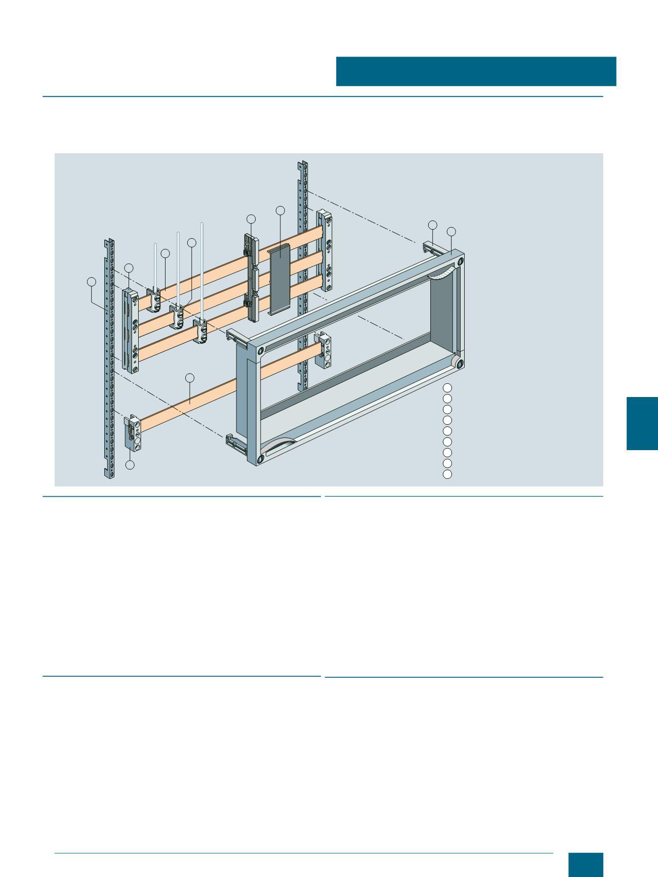
Longitudinal stays
Busbar supports, three-phase
Cu busbars
1
2
3
4
5
6
7
8
9
Terminals
Supports for blanking covers
Blanking covers
Supports
Touch protection cover
Busbar supports, single-phase
I201_13633
© Siemens AG 2014