


 17 / 38

10
Busbar Systems
8US 60 mm Busbar Systems
Infeed and connection methods
from 630 A to 1 600 A
10/17
Siemens LV 10 · 2014
* You can order this quantity or a multiple thereof.
1)
Cannot be used on a special profile up to 1 600 A.
2)
Only for 20 mm
5 mm, 20 mm
10 mm, 25 mm
5 mm, 25 mm
10 mm,
30 mm
5 mm and 30 mm
10 mm.
Terminal covers for circular conductors
(fixing to busbar)
8US1922-1GA00
For terminals up to 120 mm
2
200 mm long, 84 mm wide
}
8US1922-1GA00
1 10 units 143 0.162
For terminals up to 300 mm
2 2)
200 mm long, 270 mm wide
}
8US1922-1GA02
1 1 unit
143 0.696
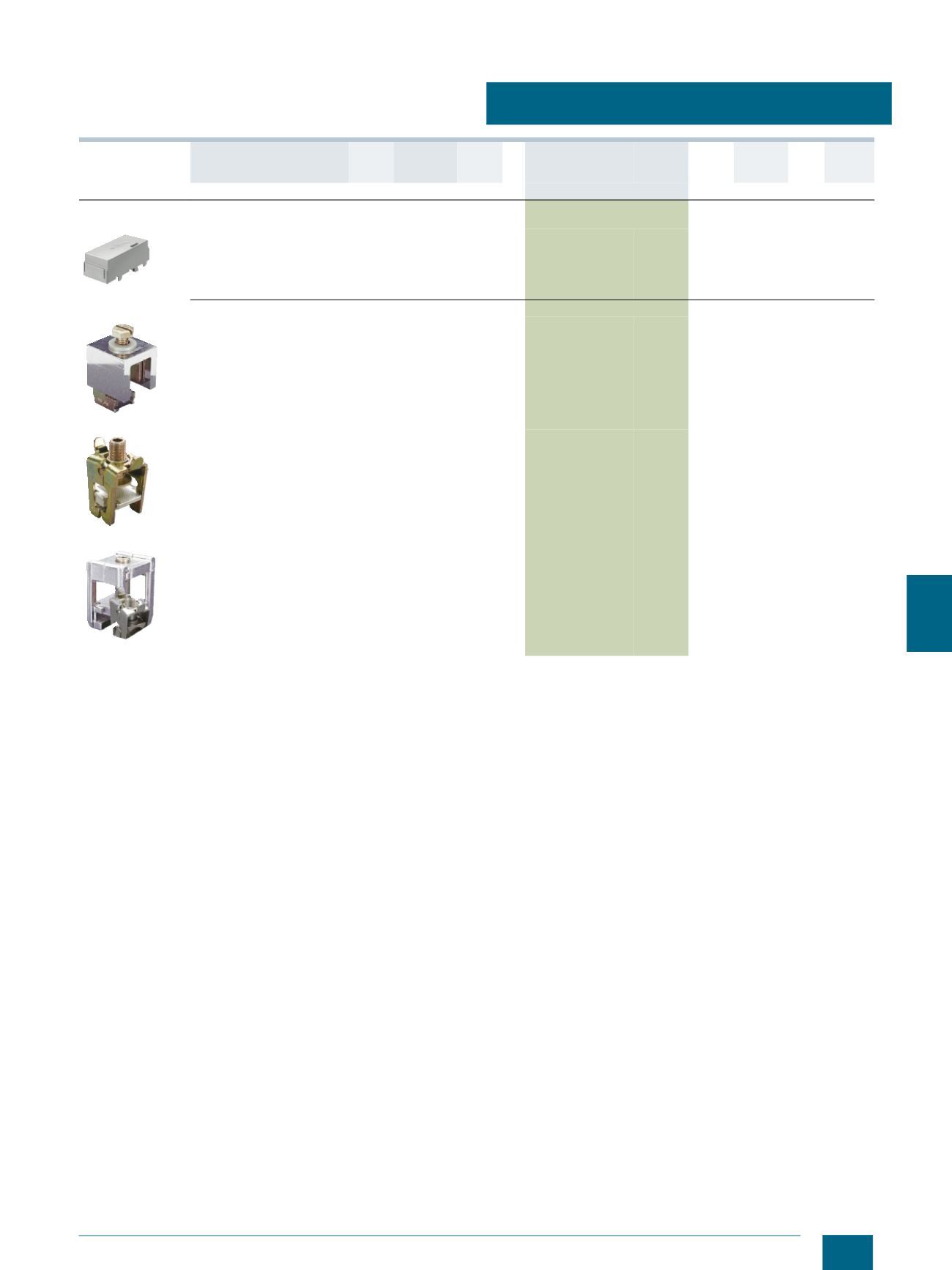
Terminals
8US1941-2AC00
For cable lugs up to 240 mm
2
,
10 mm bar thickness
(threaded bolts M10)
630
8US1941-2AC00
1 6 units 143 0.356
8US1941-2BB00
For copper bars or
laminated conductors
20 mm x 5 mm,
20 mm x 10 mm,
25 mm x 5 mm,
25 mm x 10 mm,
30 mm x 5 mm,
30 mm x 10 mm
750
8US1941-2BB00
1 6 units 143 0.329
8US1941-2BA00
For 2 x 40 mm x 10 mm,
for TT flat copper profile
30 x 10 profile
for flat bars up to 40 x 25
1250
8US1941-2BA00
1 3 units 143 0.815
Description
Max.
current
Conductor
cross-sec-
tion
Stan-
dard
DT Article No.
Price
per PU
PU
(UNIT,
SET, M)
PS*/
P. unit
PG Weight
per PU
approx.
mm
2
kg
© Siemens AG 2014