


 251 / 253

Automation products
2010
CA08103002Z-EN
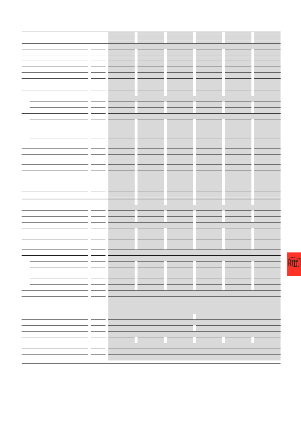
www.eaton.comMains power supply units
14/135
Input circuit
Rated input voltage
V
110 …240
AC –
–
110 …240
AC 110 …240 AC 110 …240 AC
Switch position 110
V
–
110 … 120
AC 110 … 120 AC –
–
–
Switch position 230
V
–
220 … 240
AC 220 … 240 AC –
–
–
Primary voltage range
V
85 … 264
AC –
–
85 …264
AC
85 …264
AC
85 …264
AC
Input voltage range
1)
V
100 … 350
DC –
–
100 … 350
DC 100 … 350 DC 100 … 350 DC
Switch position 110 V AC
V
–
85 … 132
AC 85 … 132 AC –
–
–
Switch position 230 V AC
V
–
184 … 264
AC 184 … 264 AC –
–
–
Switch position 230 V DC
V
–
220 … 350
DC 220 … 350 DC –
–
–
Mains frequency
Rated value
Hz
50/60
50/60
50/60
50/60
50/60
50/60
Range
Hz
47…63
47…63
47…63
47…63
47…63
47…63
Current consumption
At 110 … 240 V AC
A
Approx.
2.2 …1.2
–
–
Approx.
2.2 …1.2
Approx.
3.5 …1.6
Approx.
5.5 …2.5
At switch position 110 V AC
A
–
Approx.
4.2…4.0
Approx.
9.0…8.0
–
–
–
At switch position 230 V AC
A
–
Approx.
2.4…2.2
Approx.
4.4…4.0
–
–
–
Input power
W Normally 135
Normally 269
Normally 538
Normally 135
Normally 269
Normally 538
Inrush current limiter/i
2
t (cold start)
≦ 23 A /
ca. 0.9 A
2
s
≦ 40 A /
ca. 1.8 A
2
s
≦ 70 A /
ca. 8 A
2
s
≦ 23 A /
ca. 0.9 A
2
s
≦ 33 A /
ca. 0.2 A
2
s
≦ 40 A /
ca. 1.9 A
2
s
Mains failure bridging duration
ms
Normally ≧ 100 Normally ≧ 50
Normally ≧ 50
Normally ≧ 100 Normally ≧ 40
Normally ≧ 40
Start-up after mains voltage applied
ms
Normally ≧ 100 Normally ≧ 10
Normally ≧ 20
Normally ≧ 100 Normally ≧ 5
Normally ≧ 370
Transient overvoltage protection
Varistors
Varistors
Varistors
Varistors
Varistors
Varistors
Internal input fuse
(
device protection, not accessible)
4
AT
6.3
AT
12
AF
4
AT
6.3
AT
12
AF
Leakage current to PE
mA
< 3.5 mA
< 3.5 mA
< 3.5 mA
< 3.5 mA
< 3.5 mA
< 3.5 mA
Output circuit
L+, L+, L-, L-
Proof against short-circuit, no-load and overload
Rated output voltage
V
24
DC
24
DC
24
DC
24
DC
24
DC
24
DC
Tolerance
-1…
+5 %
-1…
+5 %
-1…
+5 %
-1…
+5 %
-1…
+5 %
-1…
+5 %
Output voltage setting range
Fixed 24 V DC
22…28
V DC; default setting 24 V ±0.5%
Rated output power
W 120
240
480
120
240
480
Rated output current T
u
≦ 60 °C
A
5
10
20
5
10
20
Peak output current (power reserves)
Tu ≦ 40 °C
A
Normally ≦ 7.25 Normally ≦ 12.25 Normally ≦ 22.5 Normally ≦ 7.25 Normally ≦ 12.25 Normally ≦ 22.5
Derating 60 °C ≦ T
u
≦ 70 °C
2.5 %
for Kelvin temperature increase
Control deviation at
Load change 10…90 %, static
Normally ±0.1 %
±0.1 %
±0.1 %
±0.05 %
±0.05 %
±0.05 %
Load change 10…90 %, dynamic
Normally ±3 %
±3 %
±3 %
±3 %
±3 %
±3 %
Controller acting time
ms
Normally 1
Normally 1
Normally 1
Normally 1
Normally 1
Normally 1
Input voltage deviation ±10 %
Normally ±0.05 % Normally ±0.05 % Normally ±0.05 % Normally ±0.05 % Normally ±0.05 % Normally ±0.05 %
Rise time 10…90 %
ms
Normally ≦ 30
Normally ≦ 5
Normally ≦ 15
Normally ≦ 30
Normally ≦ 4
Normally ≦ 12
Residual ripple and switching peaks
20
MHz normally < 50 mV
ss
Parallel connection capability
Yes, up to 5 devices for redundancy and for power increase, non symetrical current
Series connection capability
Yes, for voltage increase (max. 2 off)
Resistance to reverse feed
Yes, limited to Approx. 35 V AC
Power factor correction (PFC)
No
Yes
Status indication
OUTPUT OK: LED green
Overload characteristics
Thermal protection
Thermal protection
Response to short-circuit
Continuously with current limitation
Current limitation at short-circuit
A
Approx. 11
Approx. 19
Approx. 25
Approx. 11
Approx. 19
Approx. 25
Short-circuit protection
Proof against sustained short circuit
Overload protection
Thermal protection
Capacitive load starting
Not restricted
Notes
1)
At ≧ 264 V DC, use suitable external fuse in addition
SN3-050-BU8
SN3-100-BV8
SN3-200-BV8
SN3-050-EU8
SN3-100-EU8
SN3-200-EU8