


 46 / 221

46
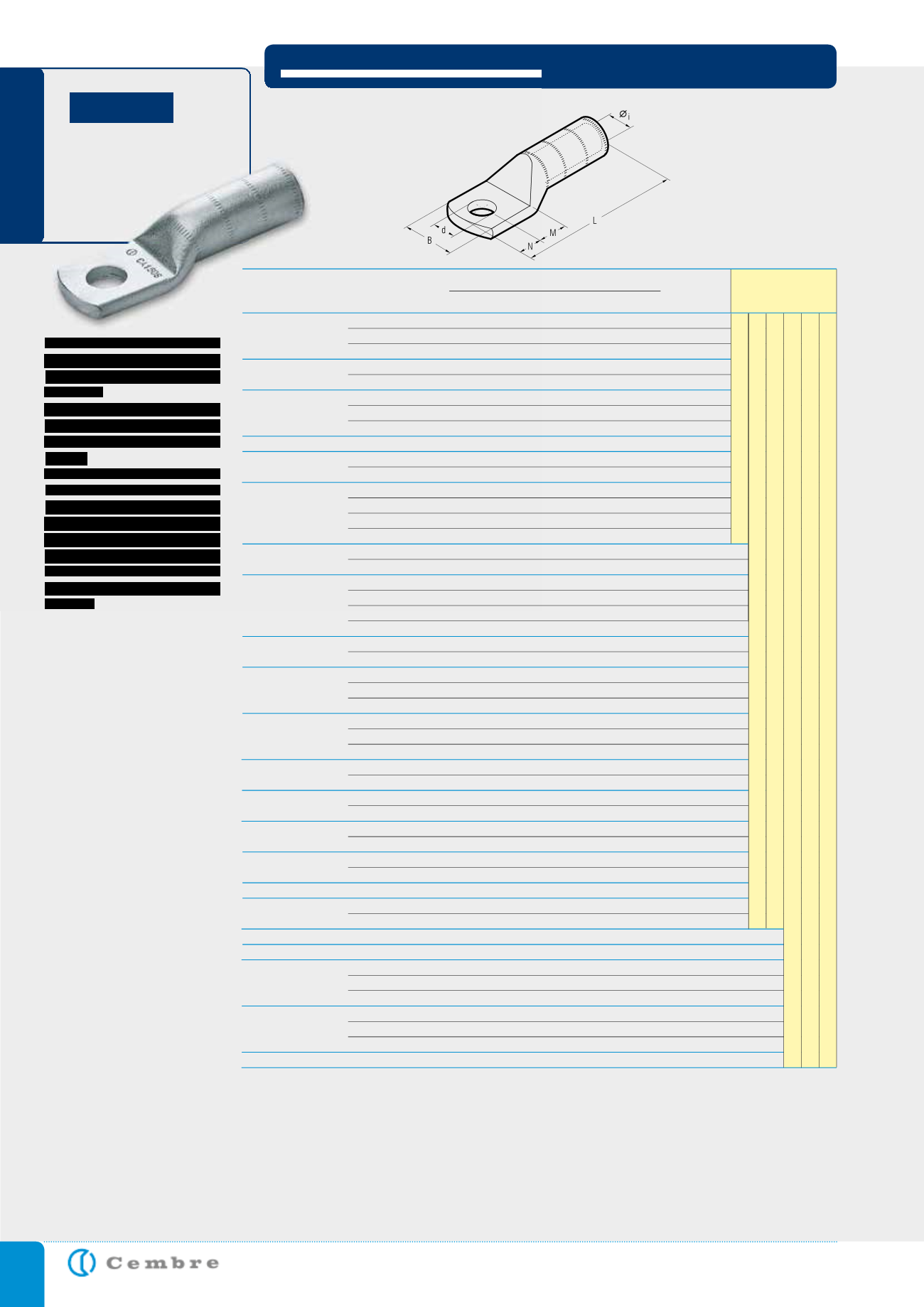
Series CA-M and 2A-M
terminals are designed for
high voltage applications up
to 33 kV.
They are manufactured
from high purity Copper
tube, annealed and Tin
plated.
The extended barrel en-
hances both electrical and
mechanical performance.
The absence of an inspec-
tion hole prevents moisture
entry into the crimped joint
and makes these terminals
suitable for outdoor appli-
cations.
Details of the appropriate
crimping tools and dies are
shown on page 184.
HIGH VOLTAGE HEAVY DUTY COPPER TERMINALS
CA-M
Hydraulic
Tools
8
CA 25-M 8
6,8 14,0
9
8
65,0
8,4
10
CA 25-M 10
6,8 18,0 13
11
72,0 10,5
12
CA 25-M 12
6,8 21,0 16
14
78,0 13,2
12
CA 40 S-M 12
8,2 21,0 16
14
79,0 13,2
16
CA 40 S-M 16
8,2 26,0 19
17
85,0 17,0
10
CA 35-M 10
8,25 21,0 13
11
73,0 10,5
12
CA 35-M 12
8,25 21,0 16
14
79,0 13,2
16
CA 35-M 16
8,25 26,0 19
17
85,0 17,0
12
CA 50 R-M 12
8,7 20,5 16
14
79,0 13,2
12
CA 50 S-M 12
9,5 21,0 16
14
79,0 13,2
16
CA 50 S-M 16
9,5 26,0 19
17
85,0 17,0
10
CA 50-M 10
9,5 21,0 13
11
73,0 10,5
12
CA 50-M 12
9,5 21,0 16
14
79,0 13,2
14
CA 50-M 14
9,5 25,0 18
16
83,0 15,0
16
CA 50-M 16
9,5 26,0 19
17
85,0 17,0
12
CA 70 S-M 12
11,0 28,0 16
14
81,2 13,2
16
CA 70 S-M 16
11,0 30,0 19
17
87,2 17,0
10
CA 70 S-M 10
11,0 26,0 13
11
75,2 10,5
12
CA 70 S-M 12
11,0 28,0 16
14
81,2 13,2
14
CA 70 S-M 14
11,0 28,0 18
16
85,2 15,0
16
CA 70 S-M 16
11,0 30,0 19
17
87,2 17,0
12
CA 95 R-M 12
12,0 28,0 16
14
91,0 13,2
14
CA 95 R-M 14
12,0 29,0 18
16
95,0 15,0
12
CA 95 S-M 12
13,5 28,0 16
14
91,0 13,2
14
CA 95 S-M 14
13,5 29,0 18
16
94,5 15,0
16
CA 95 S-M 16
13,5 30,0 20
17
97,0 17,0
10
CA 95-M 10
13,5 28,0 13
11
85,0 10,5
12
CA 95-M 12
13,5 28,0 16
14
91,0 13,2
16
CA 95-M 16
13,5 30,0 20
17
97,0 17,0
12
CA 150 R-M 12
15,0 31,0 16
14
97,0 13,2
14
CA 150 R-M 14
15,0 31,0 18
16 101,0 15,0
12
CA 120-M 12
15,0 31,0 16
14
97,0 13,2
16
CA 120-M 16
15,0 31,0 19
17 103,0 17,0
12
CA 150 S-M 12
16,5 32,0 16
14
97,0 13,2
14
CA 150 S-M 14
16,5 32,0 18
16 101,0 15,0
12
CA 150-M 12
16,5 32,0 16
14
97,0 13,2
16
CA 150-M 16
16,5 32,0 19
17 103,0 17,0
14
CA 200 R-M 14
17,0 32,5 18
16 101,0 15,0
12
CA 185-M 12
18,0 33,5 16
14
97,0 13,2
16
CA 185-M 16
18,0 33,5 19
17 103,0 17,0
14
CA 240 R-M 14
19,2 43,0 18
16 107,0 15,0
14
CA 315 R-M 14
21,5 43,0 18
16 105,0 15,0
12
CA 240-M 12
20,5 42,0 16
14 103,0 13,2
16
CA 240-M 16
20,5 42,0 19
17 109,0 17,0
20
CA 240-M 20
20,5 42,0 22
20 115,0 21,0
12
CA 300-M 12
23,0 43,5 16
14 109,5 13,2
16
CA 300-M 16
23,0 43,5 19
17 115,5 17,0
20
CA 300-M 20
23,0 43,5 22
20 121,5 21,0
14
CA 315 S-M 14
23,7 44,0 18
16 105,0 15,0
300/50
200/50
200/50
150/50
100/50
150/50
150/50
150/50
150/50
150/50
100/50
150/50
150/50
100/50
100/50
50/25
50/25
50/25
50/25
50/25
50/25
50/25
50/25
50/25
50/25
50/25
50/25
50/25
50/25
30/15
30/15
30/15
30/15
30/15
30/15
30/15
30/15
30/15
30/15
30/15
15/5
15/5
15/5
15/5
15/5
15/5
15/5
15/5
15/5
Conductor Size
(sqmm)
& Format
Ø
Stud
mm
Quantity
Box/Bag
Ø
i
B
M N L
d
D i m e n s i o n s m m
Ref.
25 R/BR/BS*
35 BR/BS*
30 RC/S ÷ 40 S
50 RC
50 S
50 BR/BS*
63 S ÷ 70 S
70 BR/BS*
80 S ÷ 95 RC
95 S ÷ 100 S
95 BR/BS*
120 RC/S ÷ 150 RC
120 BR/BS*
150 S ÷ 160 RC
150 BR/BS*
185 BR/BS*
240 BR/BS*
300 BR/BS*
160 S ÷ 200 RC
200 S ÷ 240 RC
240 S ÷ 315 RC
315 S
Conductor Format: R = Round, RC = Round Compact, S = Sector, BR = IEC228 (BS6360) Round, BS* = IEC228 (BS6360) Sector
* = Pre-rounding required, consult Cembre for appropriate die set
HT 81-U RHU 81
HT 120 and tools and heads with 130 kN crimping force
ECW-H3D
RHU 520
HT 51 RH 50 B 500E B 550E
B35-50MDE