


 41 / 221

41
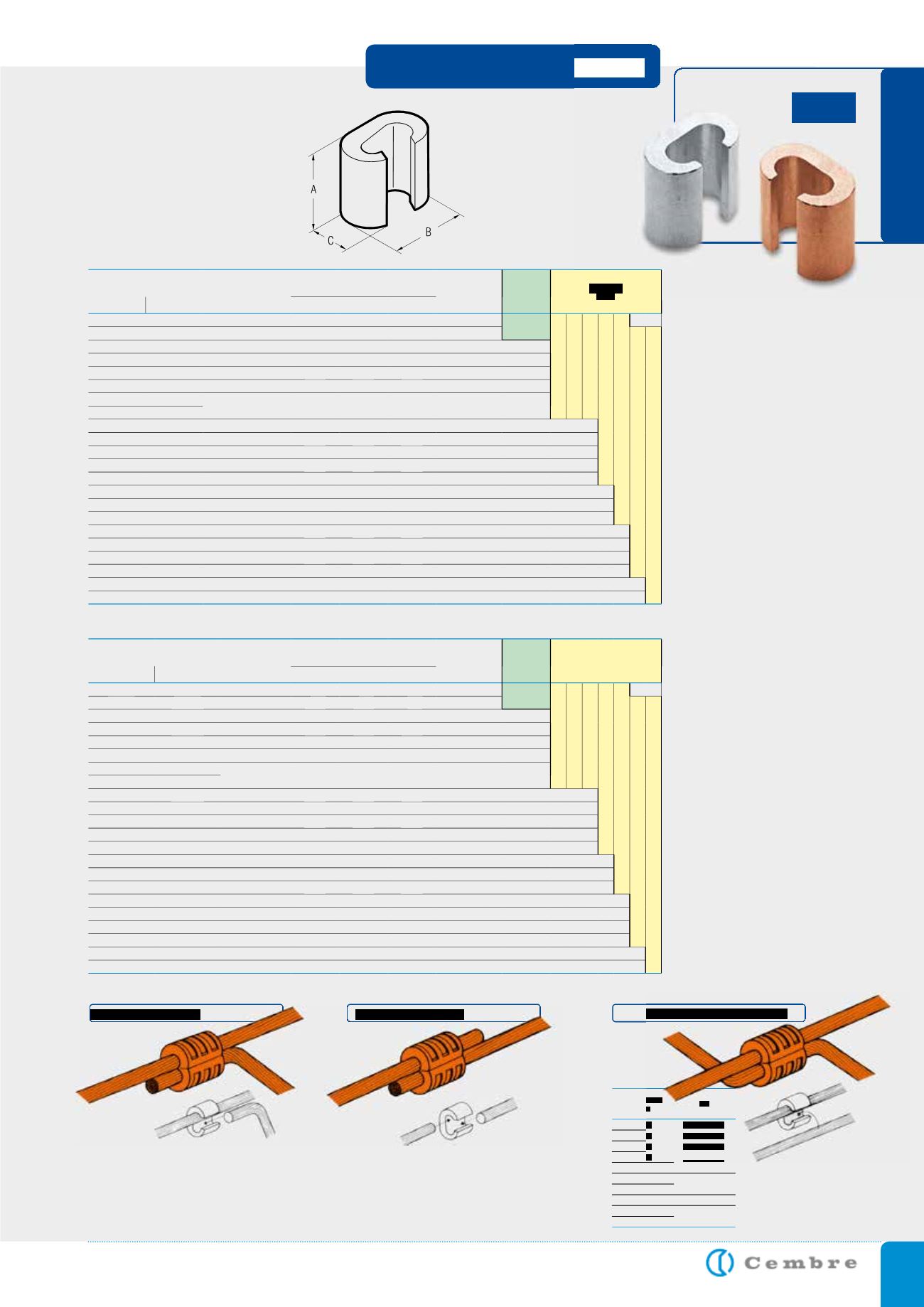
SLEEVE CONNECTORS
“C” connectors are manu-
factured from high purity
copper profiles and are
suitable for a variety of uses
either to create an earthing
network or tapping off from
overhead distribution lines.
Each connector is marked
as follows:
- Cembre trade mark
- Reference number
- Conductor size-Run
- Conductor size-Tap
- Number of crimps
- Die reference.
Details of the appropriate
crimping tools and dies are
shown on page 184.
C-C
Ref.
Conductor Size
sqmm
25-25
C 35-C 16 ST
35-35
C 35-C 35 ST
50-50
C 70-C 70 ST
63-63
C 95-C 70 ST
70-70
95-95
C 150-C 120 ST
120-120
125-125
C 150-C 150
120-120
C 185-C 95 ST
125-125
Example of tap connection
Example of joint connection
Example of joining two running conductors
Conductor Size
sqmm
Ref.
D i m e n s i o n s m m
Quantity
Box/Bag
Mechanical
Tools
Hydraulic
Tools
Run
Tap
A
B
C
6÷2,5 6÷1,5
C 6-C 6 ST
9,0
9,8
6,4
1.000/100
HP4-C10
B 35-45MDE
B 35-50MDE
HT 45-E
HT 51 RH 50 B 500E B 550E
HT 81-U RHU 81
10
10÷1,5
C 10-C 10 ST
12,0 12,6
8,4
500/100
HT 120 and tools and heads with 130 kN crimping force
ECW-H3D
16
16÷1,5
C 16-C 16 ST
17,0 19,4 12,0
500/100
25÷16 10÷1,5
C 25-C 10 ST
17,0 19,8 13,0
400/50
25
25÷16
C 25-C 25 ST
17,0 21,4 13,0
300/50
40÷35 16÷1,5
C 35-C 16 ST
21,0 24,6 15,4
200/25
40÷35 40÷25
C 35-C35 ST
21,0 26,6 15,6
200/25
50
25÷10
70÷63 25÷1,5
C 70-C 25 N ST
21,0 26,4 17,5
200/25
50
25÷4
C 50-C 25 ST
25,0 32,9 21,0
100/25
50
50÷35
C 50-C 50 ST
26,0 33,0 21,0
100/25
70÷50 40÷4
C 70-C 35 ST
28,0 33,0 21,0
100/25
70÷50 70÷35
C 70-C 70 ST
28,0 34,0 21,0
100/25
100÷95 40÷4
C 95-C 35 ST
29,0 40,6 26,0
50/25
100÷95 70÷40
C 95-C 70 ST
29,0 41,0 26,0
50/25
100÷95 100÷63
C 95-C 95 ST
29,0 41,0 26,0
50/25
125÷110 125÷25
C 120-C 120 ST
30,0 45,0 28,0
50/25
160÷150 125÷25
C 150-C 120 ST
31,0 45,0 28,0
50/25
150 150÷63
C 150-C 150 ST
30,0 45,0 28,0
50/25
185 100÷16
C 185-C 95 ST
31,0 45,0 28,0
50/25
185÷120 185÷120
C 185-C 185 ST
22,6 68,0 34,0
30/15
240÷150 120÷95
C 240-C 120 ST
22,6 68,0 34,0
30/15
Conductor Size
sqmm
Ref.
D i m e n s i o n s m m
Quantity
Box/Bag
Mechanical
Tools
Hydraulic
Tools
Run
Tap
A
B
C
6÷2,5
6÷1,5
C 6-C 6
9,0
9,8
6,4
1.000/100
HP4-C10
B 35-45MDE
B 35-50MDE
HT 45-E
HT 51 RH 50 B 500E B 550E
HT 81-U RHU 81
10
10÷1,5
C 10-C 10
12,0 12,6
8,4
500/100
HT 120 and tools and heads with 130 kN crimping force
ECW-H3D
16
16÷1,5
C 16-C 16
17,0 19,4 12,0
500/100
25÷16
10÷1,5
C 25-C 10
17,0 19,8 13,0
400/50
25
25÷16
C 25-C 25
17,0 21,4 13,0
300/50
40÷35
16÷1,5
C 35-C 16
21,0 24,6 15,4
200/25
40÷35
40÷25
C 35-C35
21,0 26,6 15,6
200/25
50
25÷10
70÷63
25÷1,5
C 70-C 25 N
21,0 26,4 17,5
200/25
50
25÷4
C 50-C 25
25,0 32,9 21,0
100/25
50
50÷35
C 50-C 50
26,0 33,0 21,0
100/25
70÷50
40÷4
C 70-C 35
28,0 33,0 21,0
100/25
70÷50
70÷35
C 70-C 70
28,0 34,0 21,0
100/25
100÷95
40÷4
C 95-C 35
29,0 40,6 26,0
50/25
100÷95 70÷40
C 95-C 70
29,0 41,0 26,0
50/25
100÷95 100÷63
C 95-C 95
29,0 41,0 26,0
50/25
125÷110 125÷25
C 120-C 120
30,0 45,0 28,0
50/25
160÷150 125÷25
C 150-C 120
31,0 45,0 28,0
50/25
150
150÷63
C 150-C 150
30,0 45,0 28,0
50/25
185
100÷16
C 185-C 95
31,0 45,0 28,0
50/25
185÷120 185÷120
C 185-C 185
22,6 68,0 34,0
30/15
240÷150 120÷95
C 240-C 120
22,6 68,0 34,0
30/15
bright surface version
tin plated version