


 47 / 221

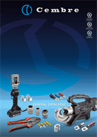
47
CA-2M and 2A-2M Copper
Tube Terminal Lugs are de-
signed for high voltage ap-
plications up to 33kV.
Manufactured from high
purity Copper tube, an-
nealed and Tin plated.
The extended barrel en-
hances electrical and me-
chanical performance.
The absence of an inspec-
tion hole prevents moisture
entry into the crimped joint.
Featuring an extended
palm with two fixing holes
at 44.5mm centres.
Details of the appropriate
crimping tools and dies are
shown on page 184.
Conductor Format: R = Round
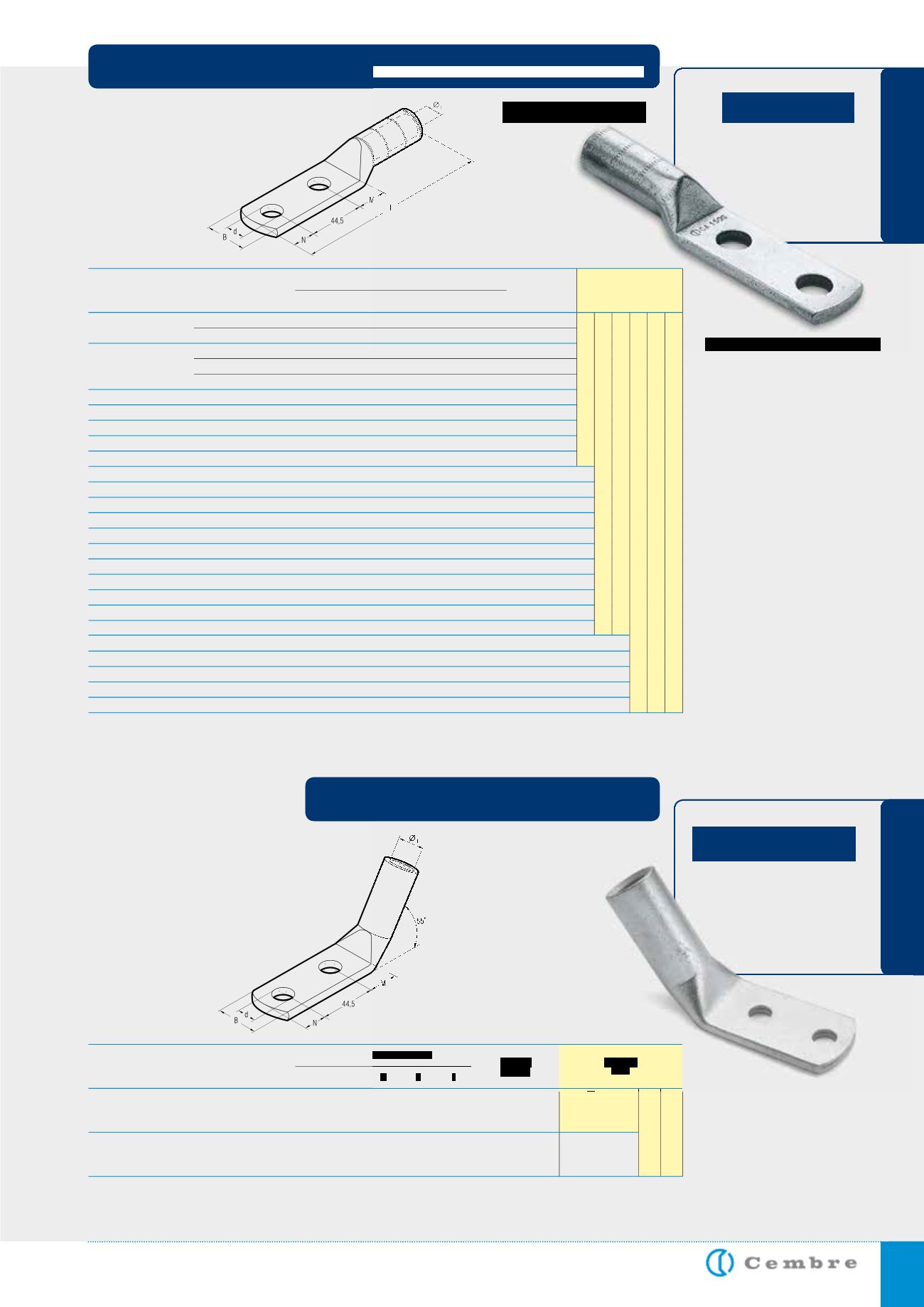
The 2A-2M/55° Copper
Tube Terminal Lugs have the
same characteristics as the
CA-2M and 2A-2M ranges,
with the additional feature of
the palm bent at 55°.
Hydraulic
Tools
14
2 A 80 - 2 M 14/55°
27,0 51,0 22
16
15
14
2 A 120 - 2 M 14/55°
33,4 61,5 22
16
15
10/5
15/3
Conductor Size
(sqmm)
& Format
Ø
Stud
mm
Quantity
Box/Bag
Ø
i
B
M N d
D i m e n s i o n s m m
Ref.
400 R
600 R ÷ 630 R
HT 120
and tools
and heads
with
130 kN
crimping
force
ECW-H3D
RHU 520
HIGH VOLTAGE HEAVY DUTY COPPER TERMINALS
two hole fixing
CA-2M
2A-2M/55°
Hydraulic
Tools
8
CA 25-2 M 8
6,8 14,0 10
11 113,5
8,4
12
CA 25-2 M 12
6,8 21,0 16
14 122,5 13,2
8
CA 25-2 M 8
6,8 14,0 10
11 113,5
8,4
10
CA 25-2 M 10
6,8 18,0 13
11 116,5 10,5
12
CA 25-2 M 12
6,8 21,0 16
14 122,5 13,2
12
CA 40 S-2 M 12
8,2 21,5 16
14 123,5 13,2
12
CA 35-2 M 12
8,25 21,5 16
14 123,5 13,2
12
CA 50 R-2 M 12
8,7 20,5 16
14 123,5 13,2
12
CA 50 S-2 M 12
9,5 21,0 16
14 123,5 13,2
12
CA 50-2 M 12
9,5 21,0 16
14 123,5 13,2
12
CA 70 S-2 M 12
11,0 27,0 16
14 127,7 13,2
12
CA 70 S-2 M 12
11,0 27,0 16
14 127,7 13,2
14
CA 95 R-2 M 14
12,0 28,0 18
16 139,5 15,0
14
CA 95 S-2 M 14
13,5 29,0 18
16 139,5 15,0
12
CA 95-2 M 12
13,5 28,0 16
14 135,5 13,2
14
CA 150 R-2 M 14
15,0 31,0 18
16 145,5 15,0
12
CA 120-2 M 12
15,0 31,0 16
14 141,5 13,2
14
CA 150 S-2 M 14
16,5 32,0 18
16 145,5 15,0
12
CA 150-2 M 12
16,5 32,0 16
14 141,5 13,2
14
CA 200 R-2 M 14
17,0 32,5 18
16 145,0 15,0
12
CA 185-2 M 12
18,0 32,5 16
14 141,5 13,2
14
CA 240 R-2 M 14
19,2 43,0 18
16 151,5 15,0
14
CA 315 R-2 M 14
21,5 43,0 18
16 149,5 15,0
12
CA 240-2 M 12
20,5 43,0 16
14 147,5 13,2
12
CA 300-2 M 12
23,0 43,0 16
14 145,5 13,2
14
CA 315 S-2 M 14
23,7 44,0 18
16 149,5 15,0
Conductor Size
(sqmm)
& Format
Ø
Stud
mm
Quantity
Box/Bag
Ø
i
B
M N L
d
D i m e n s i o n s m m
Ref.
25 R
25 BR/BS*
30 RC/S ÷ 40 S
35 BR/BS*
50 RC
50 S
50 BR/BS*
63 S ÷ 70 S
70 BR/BS*
80 S ÷ 95 RC
95 S ÷ 100 S
95 BR/BS*
120 RC/S ÷ 150 RC
120 BR/BS*
150 S ÷ 160 RC
150 BR/BS*
160 S ÷ 200 RC
185 BR/BS*
200 S ÷ 240 RC
240 S ÷ 315 RC
240 BR/BS*
300 BR/BS*
315 S
Conductor Format: R = Round, RC = Round Compact, S = Sector, BR = IEC228 (BS6360) Round, BS* = IEC228 (BS6360) Sector
* = Pre-rounding required, consult Cembre for appropriate die set
HT 81-U RHU 81
HT 120 and tools and heads with 130 kN crimping force
ECW-H3D
RHU 520
HT 51 RH 50 B 500E B 550E
B35-50MDE
HIGH VOLTAGE TERMINALS
two hole fixing - 55°