


 225 / 300

TSC-0912 - 09.10.12
Furse, Wilford Road, Nottingham, NG2 1EB • Tel: +44 (0)115 964 3700 • Email:
enquiry@furse.com• Web:
www.furse.comESP PCB/D & PCB/TN Series
Technical specification
1
Nominal voltage (DC or AC peak) measured at < 5 µA
(ESP PCB/15D, ESP PCB/30D, ESP PCB/50D, ESP PCB/110D)
and <200 µA (ESP PCB/06D).
2
Maximum working voltage (DC or AC peak) measured at
< 1 mA leakage (ESP PCB/15D, ESP PCB/30D, ESP PCB/50D,
ESP PCB/110D), < 10 mA (ESP PCB/06D) and < 10 µA
(ESP PCB/TN).
3
The maximum transient voltage let-through of the protector
throughout the test (±10%), line to line & line to earth, both
polarities. Response time < 10 ns.
4
Test to IEC 61000-4-5:2006, ITU-T (formerly CCITT) K.20,
K.21 and K.45,Telcordia GR-1089-CORE, Issue 2:2002,
ANSI TIA/EIA/IS-968-A:2002 (formerly FCC Part 68).
5
The installation and connections external to the protector
may limit the capability of the protector.
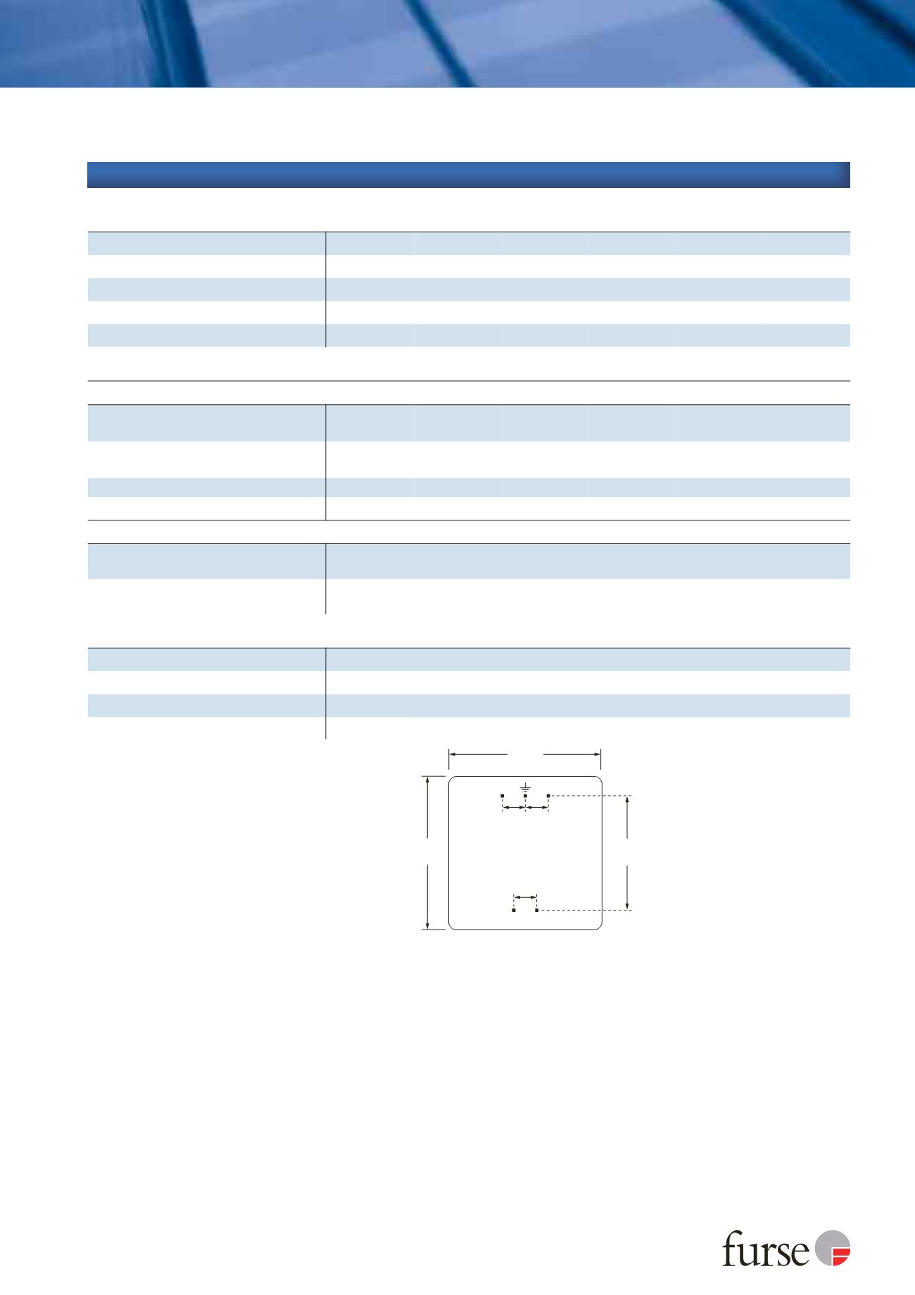
30 mm
(~1 1/2”)
22.86 mm
(0.9”)
1
2
4 3
5.08 mm
(0.2”)
5.08 mm
(0.2”)
5.08 mm
(0.2”)
Depth: 20 mm (~0.8”)
Weight: 35 g
Pins are positioned centrally
Pin 1 connects through Pin 3
Pin 2 connects through Pin 4
(Underside pin view)
30 mm
(~1 1/2”)
Electrical specification
ESP PCB/06D ESP PCB/15D ESP PCB/30D ESP PCB/50D ESP PCB/110D ESP PCB/TN
Nominal voltage
1
6 V
15 V
30 V
50 V
110 V
-
Maximum working voltage
U
c
2
7.79 V
19 V
37.1 V
58 V
132 V
296 V
Current rating
(signal)
300 mA
In-line resistance
(per line ±10%)
9.4
Ω
9.4
Ω
9.4
Ω
9.4
Ω
9.4
Ω
4.4
Ω
Bandwidth
(-3 dB 50
Ω
system)
800 kHz
2.5 MHz
4 MHz
6 MHz
9 MHz
20 MHz
Transient specification
ESP PCB/06D ESP PCB/15D ESP PCB/30D ESP PCB/50D ESP PCB/110D ESP PCB/TN
Let-through voltage
(all conductors)
3
U
p
C2 test 4 kV 1.2/50 µs, 2 kA 8/20 µs to
BS EN/EN/IEC 61643-21
12.0 V
25.0 V
44.0 V
78.0 V
155 V
395 V
C1 test 1 kV, 1.2/50 µs, 0.5 kA 8/20 µs to
BS EN/EN/IEC 61643-21
11.5 V
24.5 V
43.5 V
76.0 V
150 V
390 V
B2 test 4 kV 10/700 µs to BS EN/EN/IEC 61643-21
10.0 V
23.0 V
42.5 V
73.0 V
145 V
298 V
5 kV, 10/700 µs
4
10.5 V
23.8 V
43.4 V
74.9 V
150 V
300 V
Maximum surge current
5
D1 test 10/350 µs to
- per signal wire
BS EN/EN/IEC 61643-21
- per pair
2.5 kA
5 kA
8/20 µs to ITU-T K.45:2003, - per signal wire
IEEE C62.41.2:2002
- per pair
10 kA
20 kA
Mechanical specification
ESP PCB/D & PCB/TN Series
Temperature range
-40 to +80 ˚C
Connection type
0.64 mm (0.025”) square PCB pins, 1.2 mm diameter PCB holes recommended
Case material
ABS UL94 V-0
Dimensions