


 217 / 300

NEW
Furse, Wilford Road, Nottingham, NG2 1EB • Tel: +44 (0)115 964 3700 • Email:
enquiry@furse.com• Web:
www.furse.comESP SL LED 4-20 mA Series
NEW
TSC-0912 - 09.10.12
Technical specification
The ESP SL ‘Slim Line’ Series is also available for protection of systems up to 110 V as well as 3-wire, RS 485, RTD & telecommunication
applications (ESP SL/3W, ESP SL RS485, ESP SL RTD & ESP SL TN). The ESP SL X Series has approvals for use in hazardous areas.
1
Nominal voltage (DC or AC peak) measured at < 10 µA.
2
Maximum working voltage (DC or AC peak) measured at
< 1 mA leakage.
3
The minimum current for LED indicator operation is 2 mA.
4
At 20 mA.
5
The maximum transient voltage let-through of the protector
throughout the test (±10%), line to line & line to earth, both
polarities. Response time < 10 ns.
6
Test to IEC 61000-4-5:2006, ITU-T (formerly CCITT) K.20,
K.21 and K.45, Telcordia GR-1089-CORE, Issue 2:2002,
ANSI TIA/EIA/IS-968-A:2002 (formerly FCC Part 68).
Electrical specification
ESP SL30L/4-20
Nominal voltage
1
30 V
Maximum working voltage
U
c
2
36.7 V
Current rating
(signal)
3
75 mA
In-line resistance
(per line ±10%)
1.0
Ω
Series voltage drop
4
1.7 V
Transient specification
ESP SL30L/4-20
Let-through voltage
(all conductors)
5
U
p
C2 test 4 kV 1.2/50 µs, 2 kA 8/20 µs to
BS EN/EN/IEC 61643-21
63.0 V
C1 test 1 kV, 1.2/50 µs, 0.5 kA 8/20 µs to
BS EN/EN/IEC 61643-21
51.3 V
B2 test 4 kV 10/700 µs to BS EN/EN/IEC 61643-21
45.4 V
5 kV, 10/700 µs
6
46.3 V
Maximum surge current
D1 test 10/350 µs to
- per signal wire
BS EN/EN/IEC 61643-21
- per pair
1.25 kA
2.5 kA
8/20 µs to ITU-T K.45:2003, - per signal wire
IEEE C62.41.2:2002
- per pair
10 kA
20 kA
Mechanical specification
ESP SL30L/4-20
Temperature range
-40 to +80 ºC
Connection type
Screw terminal
Conductor size
(stranded)
4 mm
2
Earth connection
Via DIN rail or 4 mm
2
earth terminal
Case material
FR polycarbonate UL94 V-0
Weight -
unit
0.08 kg
Weight
-
packaged (per 10)
0.85 kg
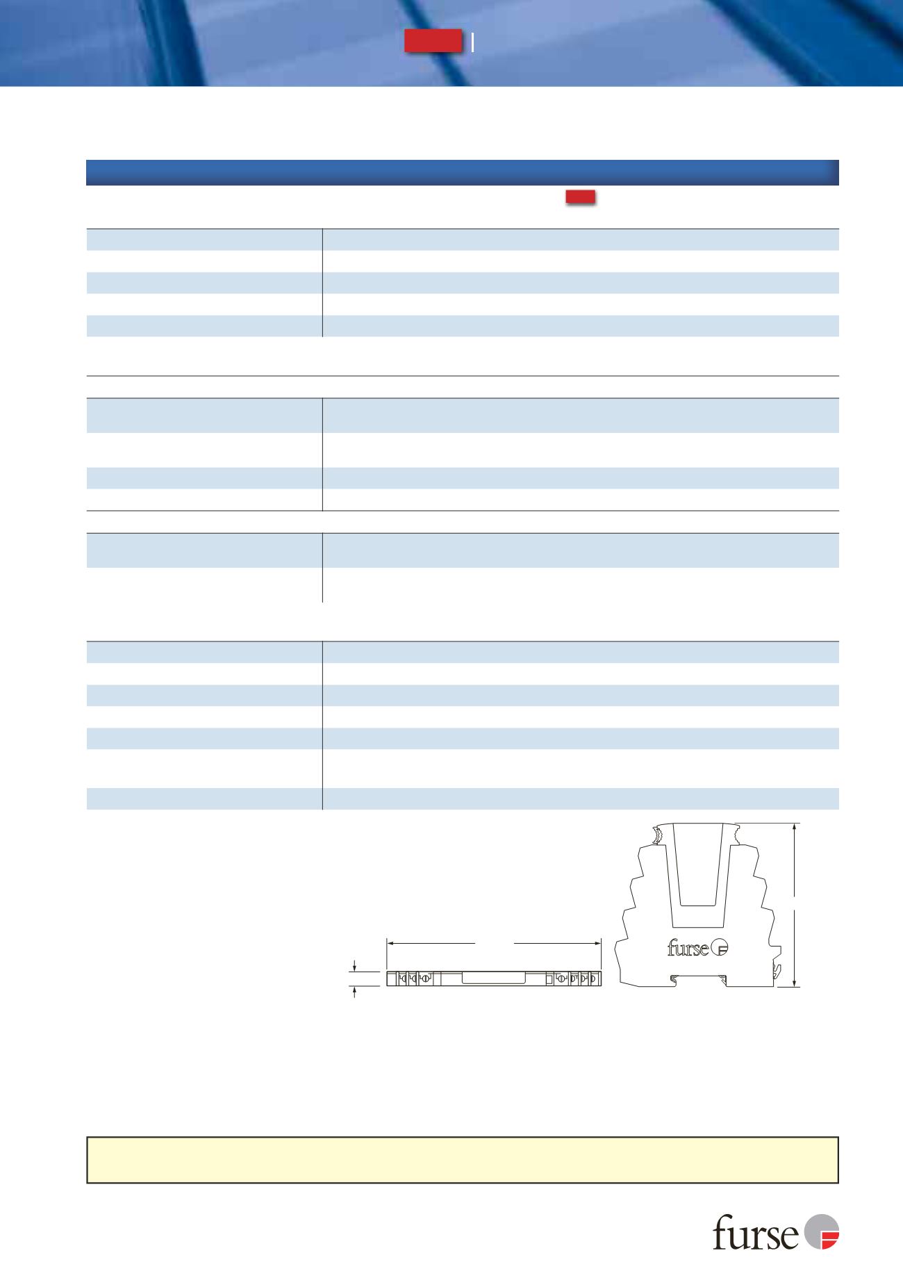
Dimensions
7 mm
104.6 mm
106.5 mm
2 S 1
2 S
E
1