


 170 / 300

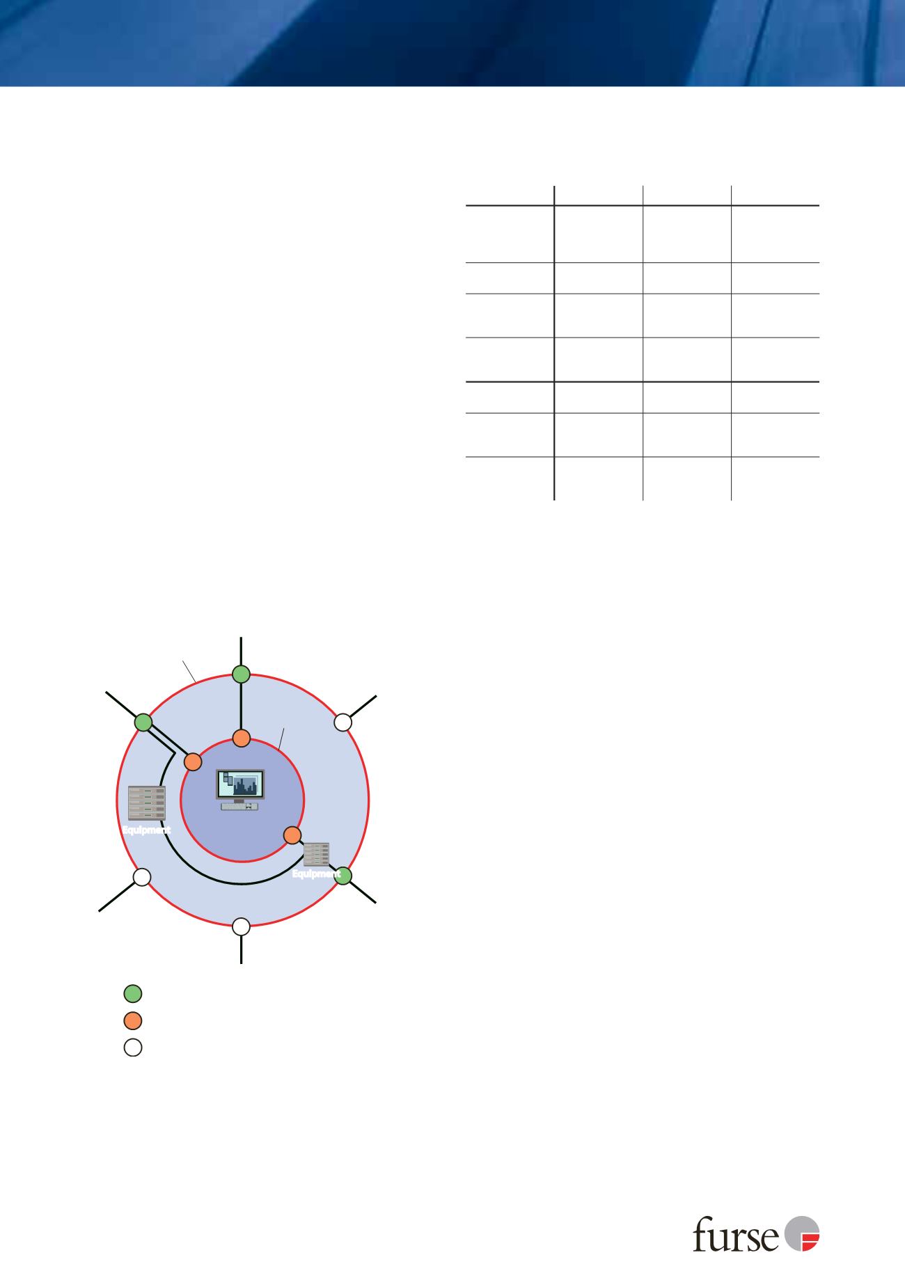
Table 1: Standardized test waveforms with peak currents used to test
SPDs at each LPZ boundary
SPD location/LPZ boundary
LPZ 0/1
LPZ 1/2
LPZ 2/3
Typical SPD
installation
point
Service Entrance
(e.g. Main
distribution board
or telecom NTP)
Sub-distribution
board
or telecom PBX
frame
Terminal
Equipment
(e.g. socket
outlet)
Mains Test
Class/SPD Type
1
I/1
II/2
III/3
Surge test
waveform
10/350 current
8/20 current
Combination
8/20 current and
1.2/50 voltage
Typical peak
test current
(per mode)
25 kA
2
40 kA
3 kA (with 6 kV)
Signal/Telecom
Test Category
1
D1
3
C2
3
C1
Surge test
waveform
10/350 current
Combination
8/20 current and
1.2/50 voltage
Combination
8/20 current and
1.2/50 voltage
Typical peak
test current
(per mode)
2.5 kA
2 kA (with 4 kV) 0.5 kA (with 1 kV)
1
Tests to BS EN 61643 series
2
Peak current (per mode) for a 3 phase SPD to protect a TN-S mains system
3
Test category B2 10/700 voltage waveform (also within ITU-T standards)
up to 4 kV peak also permissible
Furse, Wilford Road, Nottingham, NG2 1EB • Tel: +44 (0)115 964 3700 • Email:
enquiry@furse.com• Web:
www.furse.comTSC-0912 - 09.10.12
What transients are and why you need protection
Figure 7 illustrates the basic LPZ concept defined by
protection measures against LEMP as detailed in
BS EN/IEC 62305-4.
Equipment is protected against both direct and
indirect lightning strikes to the structure and
connected services, through the use of Surge
Protection Measures (SPM), formerly referred to as a
LEMP Protection Measures System (LPMS).
To achieve this reduction in LEMP severity, from
conducted surge currents and transient overvoltages,
as well as radiated magnetic field effects, successive
zones use a combination of shielding measures,
bonding of incoming metallic services such as water
and gas and the use of coordinated SPDs (further
details can be found in the Furse Guide to BS EN 62305
Protection against Lightning).
Given that the live cores of metallic electrical services
such as mains power, data and telecom cables cannot
be bonded directly to earth wherever a line penetrates
each LPZ, a suitable SPD is therefore needed.
The SPD’s characteristics at the boundary of each given
zone or installation location need to take account of
the surge energy they are to be subject to as well as
ensure the transient overvoltages are limited to safe
levels for equipment within the respective zone.
Types of SPD
BS EN/IEC 62305 deals with the provision of SPDs to
protect against both the effects of indirect lightning
strikes and high-energy direct lightning strikes.
Direct lightning strikes are protected by lightning
current or equipotential bonding SPDs (Mains Type
1 SPDs & Signal/Telecom SPDs to Test Category D)
Indirect lightning strikes and switching transients
are protected by transient overvoltage SPDs (Mains
Type 2 and Type 3 SPDs and Signal/Telecom SPDs to
Test Category C)
Lightning current or equipotential bonding SPDs
Lightning current/equipotential bonding SPDs
are designed to prevent dangerous sparking caused
by flashover.
Flashover is caused when the extremely high voltages
associated with a direct lightning strike breaks down
cable insulation. This can occur between the structural
LPS and electrical services and presents a potential fire
hazard and risk from electric shock.
Table 1, above, details the standardized test
waveforms with peak currents used to test SPDs
typically located at each zone boundary.
Boundary
of LPZ 2
(shielded room)
Boundary
of LPZ 1
(LPS)
Antenna
Electrical
power line
Water pipe
Gas pipe
Telecoms
line
Mast or
railing
LPZ 2
B
B
B
B
LPZ 1
Critical
equipment
Equipment
SPD 1/2 - Overvoltage protection
Connected service directly bonded
SPD 0/1 - Lightning current protection
Equipment
LPZ
0
Figure 7: Basic LPZ concept - BS EN/IEC 62305-4