


 176 / 300

Furse, Wilford Road, Nottingham, NG2 1EB • Tel: +44 (0)115 964 3700 • Email:
enquiry@furse.com• Web:
www.furse.comSimplified product selection
TSC-0912 - 09.10.12
Simplified product selection
All Furse ESP products are designed to provide simple
system integration whilst achieving highest levels of
effective protection against transients.
Tested in line with the BS EN 61643 standards series, ESP
protection can be selected and applied to BS EN 62305
and BS 7671 easily using the SPD product application
tables and data sheets. Key product and application
features are represented using the following symbols:
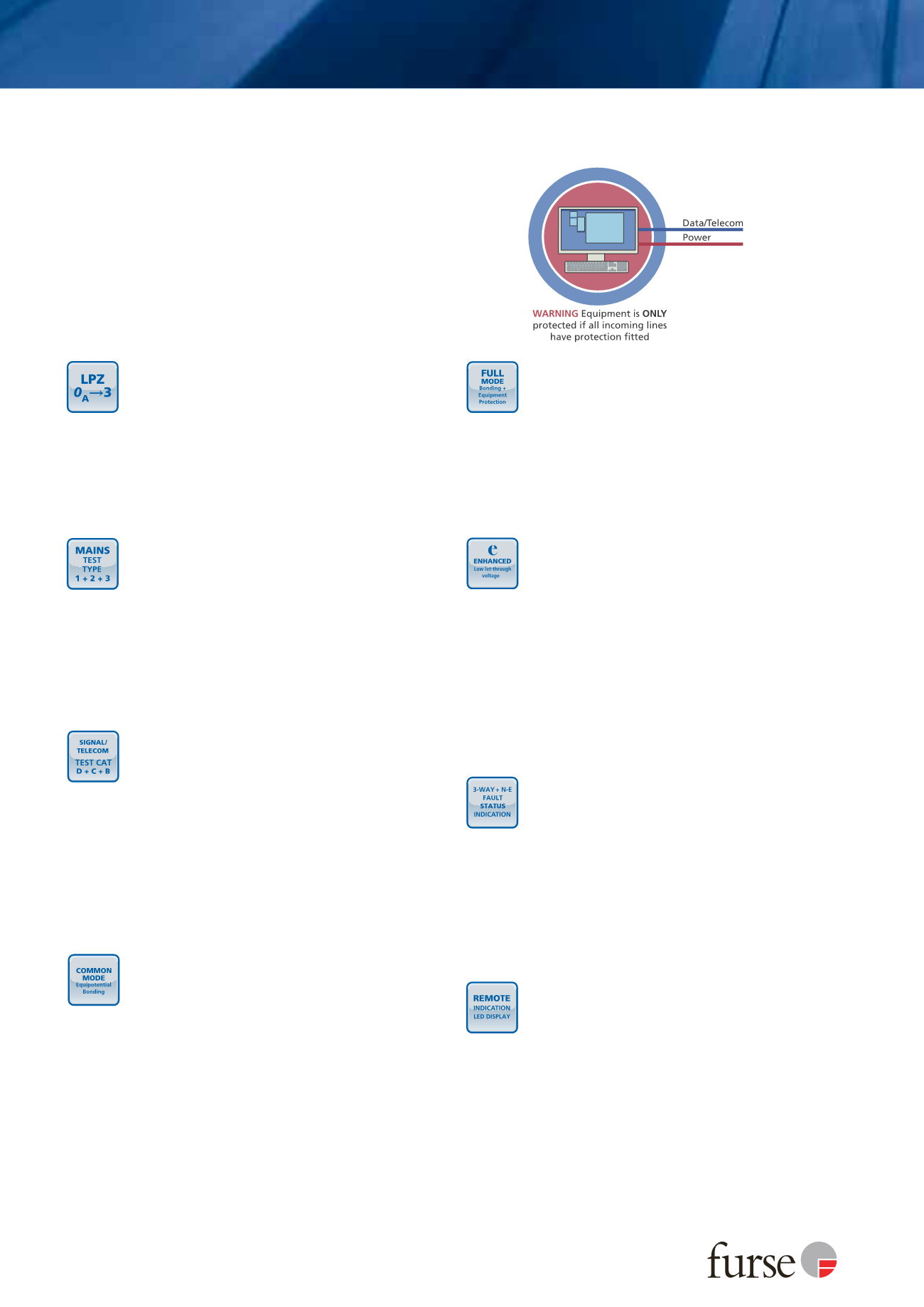
Lightning Protection Zone (LPZ)
details the
boundary (to BS EN/IEC 62305-4) or installation
point of the SPD. For example, LPZ
0
A
3 signifies
that the SPD can be installed at the service entrance
boundary and create an immediate LPZ 3 suitable
for protecting electronic equipment close to the
SPD installation.
Equipment further downstream of this location may
require additional protection, against switching
transients for example.
Mains Test Type
defines the Type of mains SPD
(BS EN 61643 Type 1, 2, 3 or I, II, III to IEC 61643)
tested with the respective test Class I (high
energy 10/350 µs current waveform), II (8/20 µs
current waveform) or III (combined 8/20 µs
current and 1.2/50 µs voltage waveform) from the
BS EN/IEC 61643 series.
Where more than one Type is stated (for combined,
enhanced Type SPDs), the SPD has been tested to
each respective test Class, with the results detailed
on its transient performance specification.
Signal/Telecom Test Category
indicates the Test
Categories (as defined in BS EN/IEC 61643 series)
that SPDs for signal and telecom systems have been
subject to, with the results detailed on the transient
performance specification.
Test Category D is a high-energy test typically using
the 10/350 µs current waveform. Test Category C is a
fast rate of rise test using the 1.2/50 µs voltage
waveform combined with 8/20 µs current waveform.
Test Category B is a slow rate of rise test using the
10/700 µs waveform, also used within ITU standards.
Enhanced SPDs tested with categories D, C and B
can offer up to LPZ
0
A
3 protection.
Common Mode
signifies that the SPD specifically
offers protection on conductors with respect to
earth. For a mains system, this would be between
phases and earth or neutral and earth. For a
data/telecom line this would be between signal
line(s) to earth.
Common mode surges can result in flashover if the
insulation withstand voltage of connected wiring or
equipment is exceeded. Flashover could lead to
dangerous sparking potentially causing fire or
electric shock risks. Equipotentially bonding Type 1
mains SPDs or Test Cat D tested signal/telecom SPDs
reduce the risk of flashover by limiting common
mode surges.
←
←
Full Mode
means that the SPD protects in all
possible modes; common mode (live conductors
with respect to earth) and differential mode
(between live conductors). For example, full mode
mains SPDs offer protection between phase(s) to
earth, phase(s) to neutral and neutral to earth.
Whilst common mode protection ensures flashover
is prevented, differential mode protection is critical
to ensure sensitive electronics are protected as well
as operational during surge activity.
Enhanced SPDs
(SPD* within BS EN 62305 series)
have lower (better) let-through voltage or
protection levels (
U
p
) and therefore further reduce
the risk of injury to living beings, physical damage
and failure of internal electronic systems.
Enhanced Type 1 mains SPDs (for a 230/400 V
system) should have a protection level
U
p
of no
more than 1600 V whilst Type 2 and Type 3 mains
SPDs should have a protection level
U
p
of no more
than 600 V in all modes when tested in accordance
with BS EN 61643 series. Enhanced signal/telecom
SPDs should typically have a protection level
U
p
no
more than twice the peak operating voltage of the
protected system.
Status Indication
for mains wire-in power
distribution SPDs is essential as they are installed in
parallel or shunt with the supply and as such could
potentially leave the system unprotected should the
SPD fail. 3-way status indication of the SPD’s
condition provides simple and clear visual inspection
and further provides advanced pre-failure warning
such that the system is never unprotected.
Furthermore warning of potentially fatal neutral to
earth faults due to incorrect earthing and wiring
faults for example is provided with additional
flashing indication.
Remote Indication
is an innovative feature that
further optimizes mains wire-in SPD protection.
A parallel or shunt installed SPD has additive
let-through voltage because of its connecting leads
that need to be kept as short as possible - ideally no
more than 25 cm. Often an SPD cannot be mounted
in its optimum position without compromising the
visibility of its status indication.
Innovative remote status indication displays
overcome this by allowing the SPD to be mounted
with short connecting leads with the separate status
display being conveniently mounted in a visible
position such as the front of a power distribution
cabinet providing convenient and effective
equipment protection.