


 168 / 300

Furse, Wilford Road, Nottingham, NG2 1EB • Tel: +44 (0)115 964 3700 • Email:
enquiry@furse.com• Web:
www.furse.comTSC-0912 - 09.10.12
What transients are and why you need protection
The information provided in these introductory
pages follows the requirements for transient
overvoltage (surge) protection provided by both
BS EN/IEC 62305 and the latest amendment
of the IET Wiring Regulations 17th Edition,
BS 7671:2008(+A1:2011).
Transient overvoltages
Transient overvoltages are short duration, high
magnitude voltages peaks with fast rising edges,
commonly referred to as surges. Often described as a
“spike”, transient voltages can reach up to 6000 V on a
low-voltage consumer network, with no more than
millisecond duration.
Lightning strikes are the most common source of
extreme transient overvoltages where total outage of
an unprotected system can occur with damage to
cabling insulation through flashover potentially
resulting in loss of life through fire and electric shock.
However, electrical and electronic equipment is also
continually stressed by hundreds of transients that
occur every day on the power supply network through
switching operations of inductive loads such as
air-conditioning units, lift motors and transformers.
Switching transients may also occur as a result
of interrupting short-circuit currents (such as
fuses blowing).
Although switching transients are of a lower magnitude
than lightning transients, they occur more frequently
and equipment failures unexpectedly occur often after a
time delay; degradation of electronic components within
the equipment is accelerated due to the continual stress
caused by these switching transients.
Transient overvoltages, whether caused by lightning or
by electrical switching, have similar effects: disruption
(e.g. data loss, RCD tripping), degradation (reduced
equipment lifespan), damage (outright equipment
failure, particularly concerning for essential services
such as fire and security alarm systems) and downtime -
the biggest cost to any business such as lost
productivity and product spoilage, staff overtime,
delays to customers and sales lost to competitors.
Protection against lightning and
switching transients
BS EN/IEC 62305 takes account of protection measures
on metallic service lines (typically power, signal and
telecom lines) using transient overvoltage or surge
protective devices (SPDs) against both direct lightning
strikes as well as the more common indirect lightning
strikes (often described as the secondary effects of
lightning) and switching transients.
Standards such as BS EN 61643 series define the
characteristics of lightning currents and voltages to
enable reliable and repeatable testing of SPDs (as well
as lightning protection components).
Although these waveforms may differ from actual
transients, the standardized forms are based upon
years of observation and measurement (and in some
cases simulation). In general they provide a fair
approximation of the real world transient.
Transient waveforms have a fast rising edge and a
longer tail. They are described through their peak
value (or magnitude), rise time and their duration (or
fall time). The duration is measured as the time taken
for the test transient to decay to half its peak value.
The figures below illustrate the common current and
voltage waveforms that are used to test SPDs for
mains, signal and telecom lines.
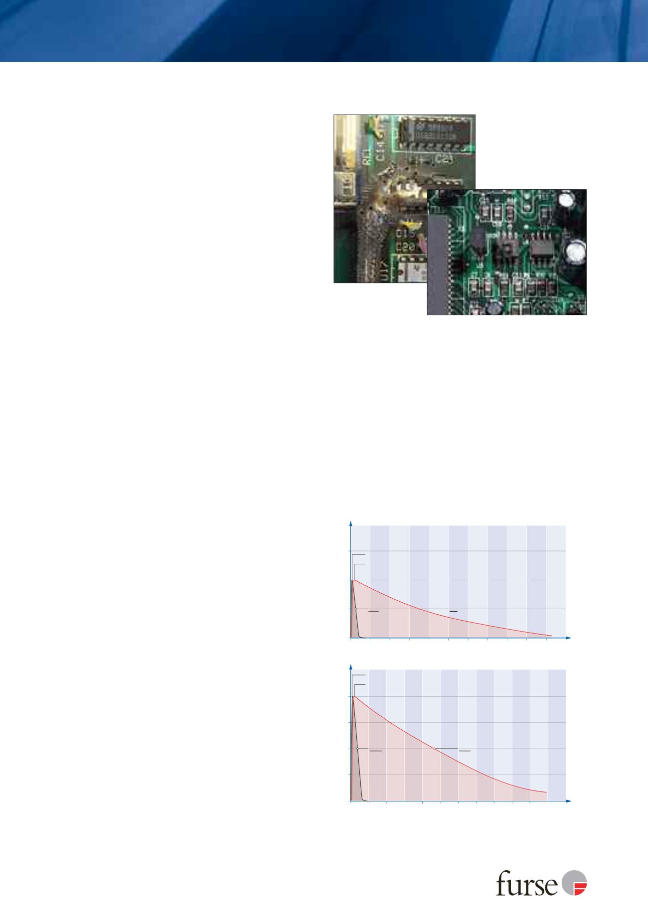
Transient overvoltage
damage to the circuit
board, left, is clear to
see, but most damage
is barely visible, as
below.
Time t (µs)
Surge Voltage (kA)
0
1
2
3
4
0
300
600
900
1200
1500
1.2/50 µs Waveform
10/700 µs Waveform
2
V
peak
@t = 50 µs
V
peak
@t = 1.2 µs
V
peak
@t = 10 µs
2
V
peak
@t = 700 µs
Figures 1 & 2: The common current and voltage waveforms used to
test SPDs for mains, signal and telecom lines
Surge Current (kA)
0
10
20
30
0
200
400
600
2
800
1000
Time t (µs)
8/20 µs Waveform
I
imp
@t = 350 µs
10/350 µs Waveform
2
I
max
@t = 20 µs
I
max
@t = 8 µs
I
imp
@t = 10 µs