


 384 / 413

2
1
3
4
5
6
7
8
9
10
8/34
Appendices
Power supplies and transformers
Phaseo
Regulated switch mode power supplies
Function modules: solutions to power outages
Selection grid
Continuity of service: Voltage holding in the event of a power outage
(
continued)
For applications that are sensitive to unintended stopping, the
ABL 8
range of
Function modules offers a solution comprising:
b
Electronic switch mode power supply and Buffer module for holding times t2 up to
two seconds
b
Electronic switch mode power supply, Battery control module and Battery module
for holding times t2 of between two seconds and a few hours
These solutions are used to supply voltage after loss of the line supply, thus enabling
saving of current values or fallback of some actuators supplied with 24 V
c
.
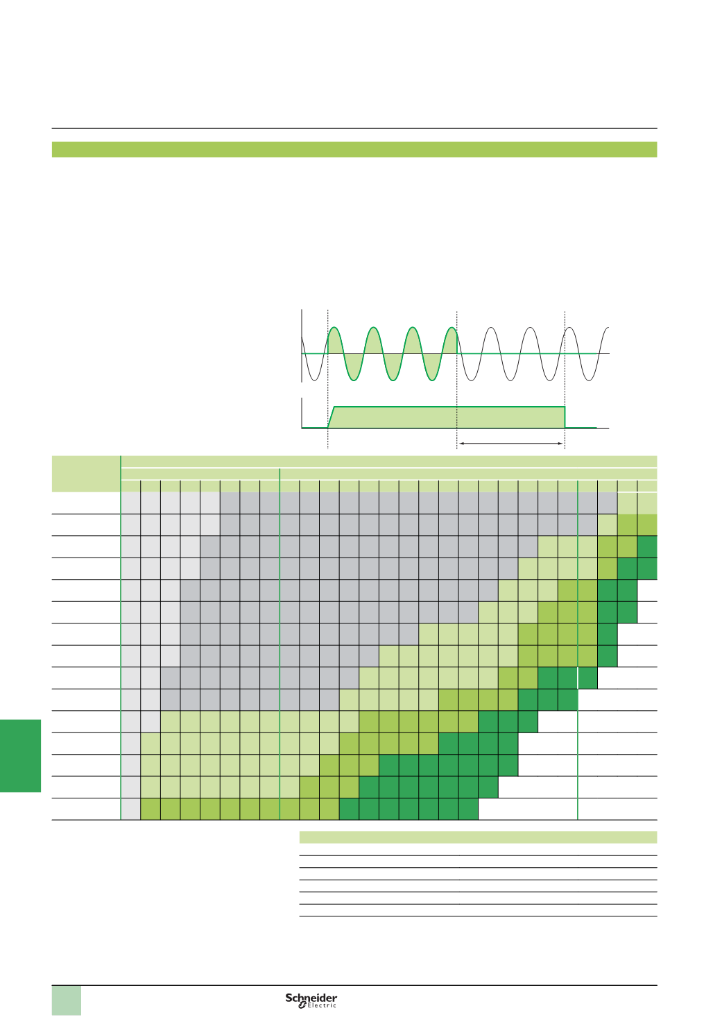
The table below indicates the possible holding times according to the equipment
combinations and the current required.
Holding current Holding time t2
Seconds
Minutes
Hours
0.1 0.2 0.5 1 2 5 10 30 1 2 3 4 5 6 7 8 9 10 15 20 30 40 50 1 2 3 5
1
A
1 1 1 1 1 2
+4 2+4 2+4 2+4 2+4 2+4 2+4 2+4 2+4 2+4 2+4 2+4 2+4 2+4 2+4 2+4 2+4 2+4 2+4 2+4 2+5 2+5
2
A
1 1 1 1 1 2
+4 2+4 2+4 2+4 2+4 2+4 2+4 2+4 2+4 2+4 2+4 2+4 2+4 2+4 2+4 2+4 2+4 2+4 2+4 2+5 2+6 2+6
3
A
1 1 1 1 2
+4 2+4 2+4 2+4 2+4 2+4 2+4 2+4 2+4 2+4 2+4 2+4 2+4 2+4 2+4 2+4 2+4 2+5 2+5 2+5 2+6 2+6
2
+6
+6
4
A
1 1 1 1 2
+4 2+4 2+4 2+4 2+4 2+4 2+4 2+4 2+4 2+4 2+4 2+4 2+4 2+4 2+4 2+4 2+5 2+5 2+5 2+5 2+6
2
+6
+6
2
+6
+6
5
A
1 1 1 2
+4 2+4 2+4 2+4 2+4 2+4 2+4 2+4 2+4 2+4 2+4 2+4 2+4 2+4 2+4 2+4 2+5 2+5 2+5 2+6 2+6
2
+6
+6
2
+6
+6
6
A
1 1 1 2
+4 2+4 2+4 2+4 2+4 2+4 2+4 2+4 2+4 2+4 2+4 2+4 2+4 2+4 2+4 2+5 2+5 2+5 2+6 2+6 2+6
2
+6
+6
2
+6
+6
7
A
1 1 1 2
+4 2+4 2+4 2+4 2+4 2+4 2+4 2+4 2+4 2+4 2+4 2+4 2+5 2+5 2+5 2+5 2+5 2+6 2+6 2+6 2+6
2
+6
+6
8
A
1 1 1 2
+4 2+4 2+4 2+4 2+4 2+4 2+4 2+4 2+4 2+4 2+5 2+5 2+5 2+5 2+5 2+5 2+5 2+6 2+6 2+6 2+6
+6
2
+6
+6
10
A
1 1 2
+4 2+4 2+4 2+4 2+4 2+4 2+4 2+4 2+4 2+4 2+5 2+5 2+5 2+5 2+5 2+5 2+5 2+6 2+6
2
+6
+6
2
+6
+6
2
+6
+6
15
A
1 1 2
+4 2+4 2+4 2+4 2+4 2+4 2+4 2+4 2+4 2+5 2+5 2+5 2+5 2+5 2+6 2+6 2+6 2+6
2
+6
+6
2
+6
+6
2
+6
+6
20
A
1 1 2
+5 2+5 2+5 2+5 2+5 2+5 2+5 2+5 2+5 2+5 2+6 2+6 2+6 2+6 2+6 2+6
2
+6
+6
2
+6
+6
2
+6
+6
25
A
1 3
+5 3+5 3+5 3+5 3+5 3+5 3+5 3+5 3+5 3+5 3+6 3+6 3+6 3+6 3+6
3
+6
+6
3
+6
+6
3
+6
+6
3
+6
+6
30
A
1 3
+5 3+5 3+5 3+5 3+5 3+5 3+5 3+5 3+5 3+6 3+6 3+6
3
+6
+6
3
+6
+6
3
+6
+6
3
+6
+6
3
+6
+6
3
+6
+6
3
+6
+6
35
A
1 3
+5 3+5 3+5 3+5 3+5 3+5 3+5 3+5 3+6 3+6 3+6
3
+6
+6
3
+6
+6
3
+6
+6
3
+6
+6
3
+6
+6
3
+6
+6
3
+6
+6
40
A
1 3
+6 3+6 3+6 3+6 3+6 3+6 3+6 3+6 3+6 3+6
3
+6
+6
3
+6
+6
3
+6
+6
3
+6
+6
3
+6
+6
3
+6
+6
3
+6
+6
Function modules
Reference
Code
40
A Buffer module
ABL 8BUF24400
1
20
A Battery control module
ABL 8BBU24200
2
40
A Battery control module
ABL 8BBU24400
3
3.2
Ah Battery module
ABL 8BPK24A03
4
7
Ah Battery module
ABL 8BPK24A07
5
12
Ah Battery module
ABL 8BPK24A12
6
Note:
Several Buffer modules (up to a maximum of three) can be connected in parallel to
increase the immunity time. The times given in the table above (boxes marked 1) should be
multiplied by the number of modules used (2 or 3).
t2
t
t
Input voltage
Output voltage