


 57 / 356

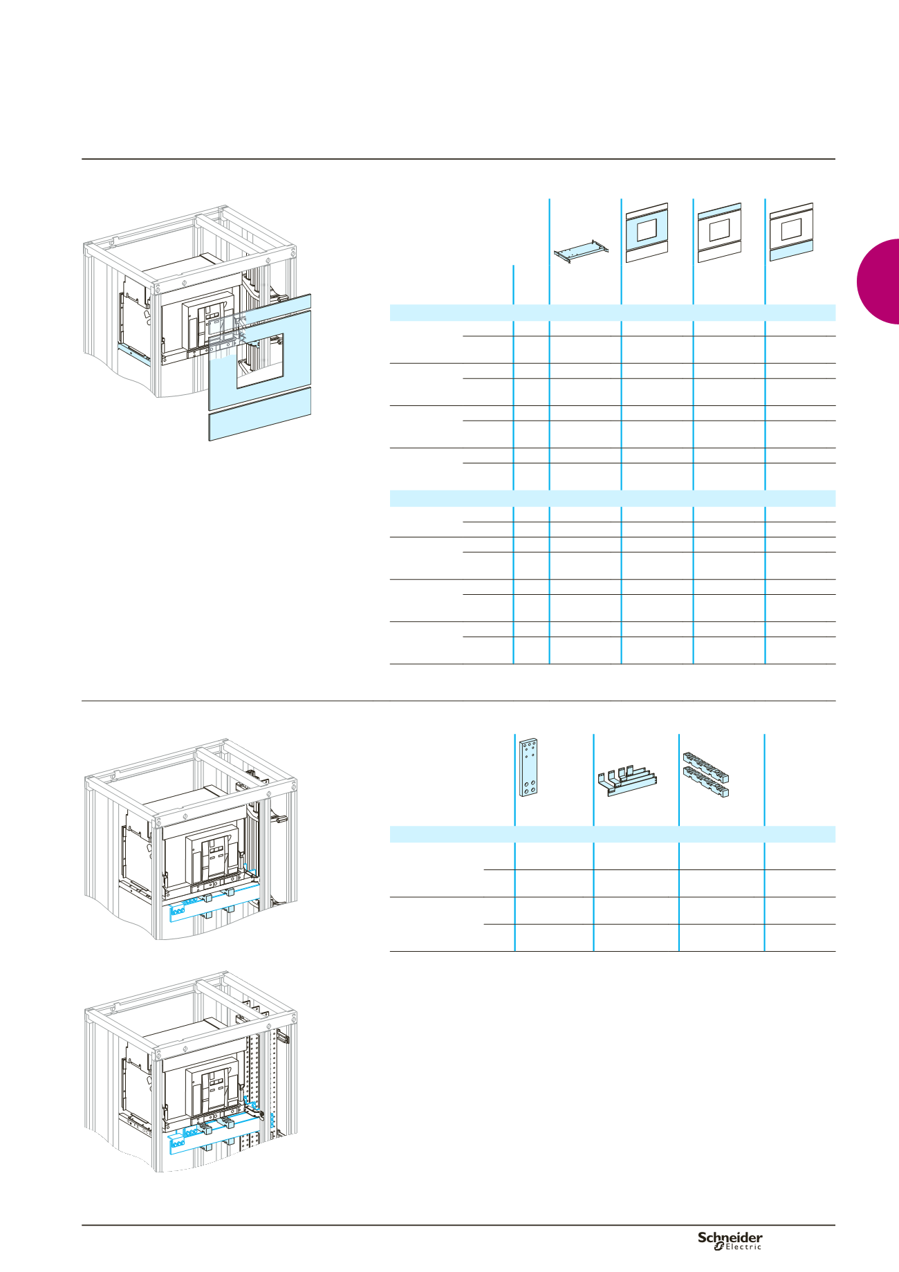
Functional units
Device installation
DD380644
DD380836
DD380833
DD380834
DD380835
Device
No. of
vert.
mod.
Mounting
plate
Cut-out
front plate
Upstream
front plate
Downstream
front plate
Fixed device
NW08/16
front conn.
cables 18
03500
03711
03804
03805
Canalis 27
03500
03711
03805+
03804 x 2
03805
NW08/16
rear conn.
cables 14
03500
03711
03805
Canalis 16
03500
03711
03804+
03803
NW20/32
front conn.
cables 19
03500
03711
03805
03805
Canalis 28
03500
03711
03804 +
03805 x 2
03805
NW20/32
rear conn.
cables 14
03500
03711
03805
Canalis 16
03500
03711
03804 +
03803
Drawout device
NW08/16
front conn.
cables 19
03500
03710
03804
03805
Canalis 27
03500
03710
03804 x 3 03805
NW08/16
rear conn.
cables 15
03500
03710
03805
Canalis 17
03500
03710
03804 +
03803
NW20/32
front conn.
cables 20
03500
03710
03805
03805
Canalis 28
03500
03710
03805 +
03804 x 2
03805
NW20/32
rear conn.
cables 15
03500
03710
03805
Canalis 17
03500
03710
03804 +
03803
Distribution
Flat or Linergy busbars
DD380681
DD380837
DD380839
DD380840
Device
Front
connectors
Connection
Free support for
BB connection
Cover for BB
connection
l
Fixed/drawout device
NW08/16
3P
b
must be made
(2)
04662 x 2
(1)
04926 +
04927
4P
b
must be made
(2)
04662 x 2
(1)
04926 +
04927
NW20/32
3P
b
must be made
(2)
04662 x 2
(1)
04926 +
04927
4P
b
must be made
(2)
04662 x 2
(1)
04926 +
04927
(1)
For an Icw
u
75 kA rms, use three free supports (04662 x 3).
(2)
For the connection to flat busbars > 1600 A, order one joint per phase:
v
1 joint for busbars, W = 50/60 mm (04640)
v
1 joint for busbars, W = 80/100 mm (04641)
Note:
To make measurements:
install the CTs preferably upstream, on the supply terminal extension bars
or install the CTs on the horizontal busbars (busbar connection). In this case, add one module
and a plain front plate (03801)
or install a Micrologic control unit capable of displaying the values.
Selection of Linergy busbars
: see page B-11.
Selection of flat busbars
: see page B-18.
b
b
b
DD383808
Masterpact NW08 to NW32
Circuit breakers
A-5